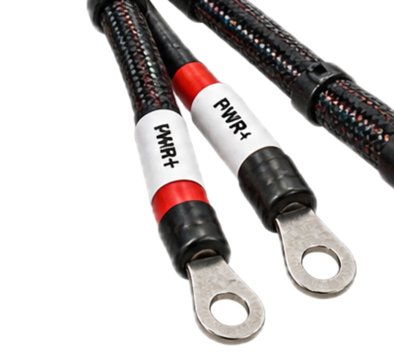
A payload draws its power from the carrier it rides on. The feed that brings it is the heaviest conductor at the seam and the one that does the most damage when it is wrong. The data bus reads its traffic inside the field the feed makes when it switches. The safety interlock is trusted on the assumption that the feed is dead when the carrier says it is dead. The bond is only a bond if the feed's return leaves it alone. So the feed is engineered with the other three in view, and built as one part of a matched set.
The mechanism
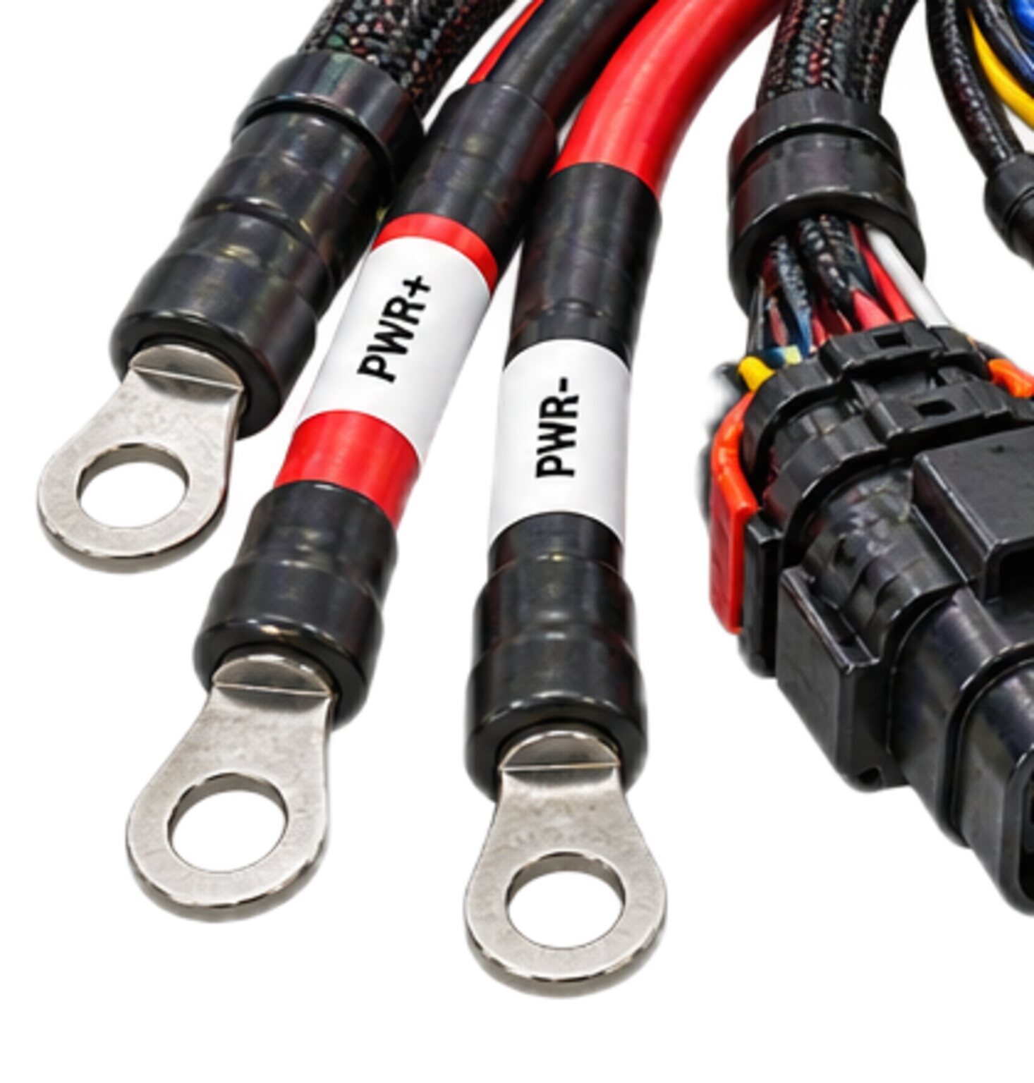
Physically this harness is a pair. One conductor carries the feed from the carrier's distribution to the payload's inlet, and one conductor of the same size carries it back. They are laid together for the whole run, twisted or bound tight as the drawing says, so that the current going out and the current coming back travel side by side and the field of one cancels the field of the other outside the pair. A feed whose return takes a different route through the carrier is not a pair. It is a loop, and everything laid across that loop sits inside the feed's field.
The conductor is stranded, because a solid conductor at a vibrating end work-hardens and breaks inside insulation that still looks whole. Its size is stated on the drawing by the engineer who owns the interface, from the load the interface declares and the length the walk fixes. The shop does not choose it and does not round it. Over the pair sits a jacket, and a braid or sleeve against abrasion where the drawing calls for it. The feed is shielded only if the interface says so, and then the shield is a shield and not the return.
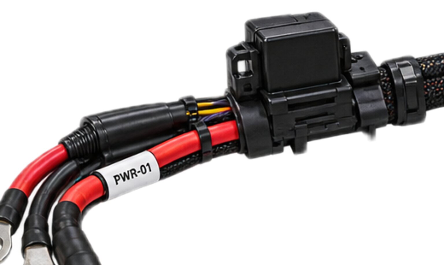
At each end the pair lands in its own shell. The carrier end mates to the receptacle where the carrier's distribution hands over a circuit already protected and already switched; the payload end mates to the payload's inlet. Each contact is sized for the conductor crimped into it and seated in the cavity the cavity map assigns.
The topology is a line from one source to one load, with no branch. If the interface lets a second payload take power, that is a second feed on the drawing with its own protection, not a splice in this one. A splice is a joint with no shell, no strain relief and no label, hidden inside a jacket where nobody will find it until it fails.
What it is engineered to
The interface is a promise in each direction. The carrier promises a feed that is protected at its source, switched under the carrier's own control, and dead when the carrier says it is dead. The payload promises to consume what it is given, to report its state into the interlock chain, and never to push power back onto the feed.
Protection lives on the carrier side, at the source, because a protective device only protects what is downstream of it. Put it at the payload end and the whole harness is upstream of its own protection. The breaker lives in the panel, not in the lamp. The feed conductor is sized so that the protection at the source opens before a fault at the far end can harm the conductor's insulation. That relationship, conductor to protection, is what the drawing fixes, and a conductor too small for its protection is a fuse with a jacket on it.
The payload does not turn its own feed on. The carrier applies power only after the interlock chain has been read and found closed, and removes it when the chain opens: the safety chain is proved before power is applied, not after. That order is why the feed and the interlock never share a shell: the interlock has to be able to say the payload is safe while the payload is entirely dead. A live contact in the same shell as a safety contact is one bent pin away from a chain that reads closed when it is open.
When the feed switches under load, the bus beside it feels it. At turn-on the payload's input takes a step of current, and the step makes a field around the conductor. At turn-off the current does not want to stop, and the voltage across the opening switch rises until the switch's own clamp catches it. A data pair twisted with its own return sees that event on both conductors alike and rejects it. A pair running parallel to a feed whose return went another way, or an untwisted length at a connector, sees it on one conductor more than the other, and the difference is a corrupted frame. So the pair is kept tight so its field stays inside it, and the bus is kept out of its bundle.
The return is a conductor, not a structure. It is the same size as the feed, it lands in its own cavity, and it is the only path the load current takes home. The airframe, the bus shield and the bond are not the return. A return that finds its own way home through a mounting bolt puts load current through a joint designed to hold a payload on, and moves the bus's reference with every change in load.
The payload never sources power onto the feed. A payload that carries its own storage has to block the path back to the carrier, and the interface puts that blocking in the payload, not in the harness; the harness carries no active part. The carrier's switch has to be the only thing that decides whether the feed is live, because the interlock trusts that, and so does the person who watched the carrier switch the payload off and then reached in.
The joint has to survive vibration at both ends, the temperature swing between a cold ramp and a warm bay, the moisture that condenses inside a shell mated cold, and a person mating it in the dark with gloves on. The bend at the fixed end is the drawing's bend, because a bend tighter than the drawing at a fixed end does not fail on the bench. It fails later, intermittently, on a machine in the field.
Safety circuits never share a bundle, a splice or a shell with power.
The discipline applied to this harness
Safety circuits never share a bundle, a splice or a shell with power. On this harness that sentence is the whole of segregation. The feed runs in its own bundle, the interlock in its own, the bus in its own, and the formboard holds the spacing between them so it is the same on every assembly. Where the feed has to cross the bus it crosses at a right angle; it never runs alongside.
The cavity map is part of the drawing and the shop builds to it as drawn: the feed and its return in the power shell, the interlock contacts in the interlock shell. Where an interface puts several shells on one mating face, the zoning inside the power shell keeps the feed and its return together in the cavities furthest from the interlock shell. Cavities the interface leaves empty are plugged, because an open cavity is an invitation to add a circuit the drawing never saw. A cavity map that puts a safety contact in the power shell is returned unsigned, with the objection marked on it.
Shielding and bonding on a feed are mostly refusals. The jacket is not a shield. The shield, where there is one, is not the return. The harness does not bond the payload to the carrier; the ground and bond harness does that, on purpose, through one path that is drawn.
Connectors are sealed to what the interface calls for, keyed so the power plug cannot be pushed onto the interlock receptacle by someone sure that it fits, and fitted with a backshell that takes the pull so the crimp carries none. Each contact is crimped with the tool for that contact and pull-checked. Sectioning is destructive, so it is done on the sacrificial samples the drawing calls for and not on a contact that ships. The bend at each fixed end is the drawing's bend, and no tie is pulled tight enough to change the pair's shape under it.
The feed and the return carry their circuit identity from one shell to the other. They are marked differently from one another at both ends and along the run, so a person at the carrier can tell which is which without a meter.
Test on this harness asks three things of every finished assembly before it leaves. Continuity asks whether the feed is one conductor from shell to shell, and the return likewise. Polarity asks whether each lands in the cavity the map assigns and no other. Isolation asks whether the feed, the return and the shield, which must never meet inside the harness, are in fact separate from one another and from everything else in the set. The crimps in the run it came from were pull-checked and sectioned on the samples the drawing calls for, and that result is on the record with the assembly. What each test is set to is stated on that assembly's own drawing by the engineer responsible for it, and nowhere else.
Done badly, this harness presents in known ways. A feed undersized for its protection runs warm, softens at its tightest bend and chafes through into whatever it touches first, which in a mixed bundle is the interlock. A return through structure moves the bus reference, and the bus drops frames every time the payload does anything. A live contact in the safety shell reads as a closed chain when the chain is open. A back-fed feed is live with the carrier switched off, and the person who trusted the switch finds out with a hand.
How it is bought
This harness is bought from an issued interface specification or drawing set. Nothing is fabricated until the drawing is signed. You send the specification that owns the interface, or the drawing set, and the shop performs the takeoff from it: conductor, contact, shell, backshell, seal, jacket, plug and marker, with their quantities. The components we specify carry their own certification. The approval route for a finished, project-specific assembly is confirmed with the certifying body for that assembly before it is built, and we tell you where yours sits before we build it, not after. CSA and the Canadian Electrical Code govern any assembly built for sale or installation in Canada.
Then the shop drawing. It carries the pair, the cavity map, the marking, the bend at each fixed end, the strain relief and the tests, and it is signed by the engineer who owns the interface before anything is cut. Where the interface is silent on something the drawing needs, the silence goes back as a question, not a guess. A value nobody measured never reaches a wire.
Then the walk. Lengths are fixed by walking the run on the carrier and the payload, with the shells in hand and the bend at each end in view, not by scaling a model. The walk produces the formboard, and the formboard is what makes the second assembly the same as the first.
Then the build, and with it the per-assembly record: the serial, the lots of conductor and contact that went into it, the crimp tool and its check, the result of each test on that assembly and the person who ran it.
Then the manufacturing detail goes back to whoever owns the design. We build to your issued set and we return the manufacturing detail: the formboard, the cut list, the cavity map as built and the test record, so the design owner holds the harness as built and not only as intended.
- We do not size a feed from a load someone remembers.
- We do not quote from a photograph of a connector.
- We do not put an active part in a harness, and we do not build a power feed that shares a shell with a safety contact, whoever asks.
- Start by sending the interface specification or the drawing set to enquiries.
- If you have neither yet, send what you have, and the reply is the list of what the drawing needs before it can be signed.