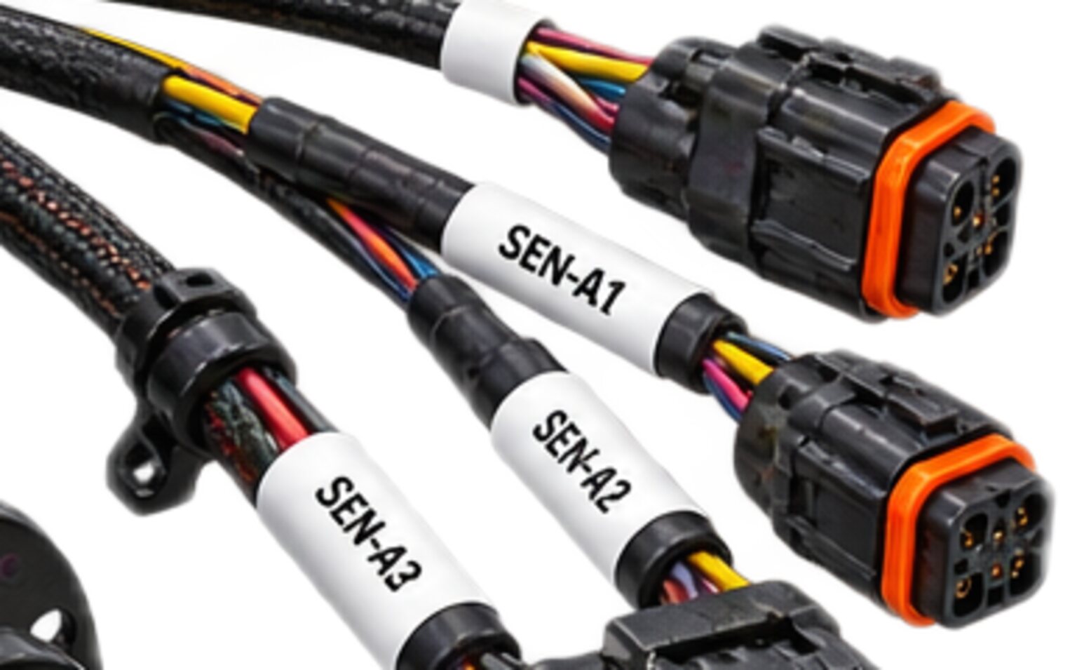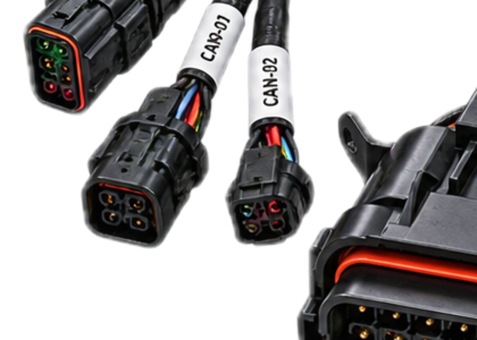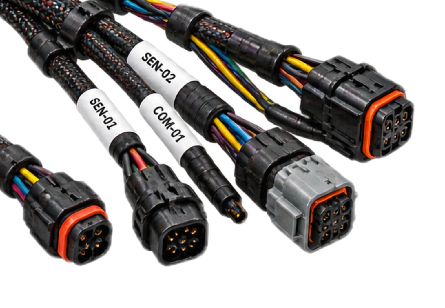
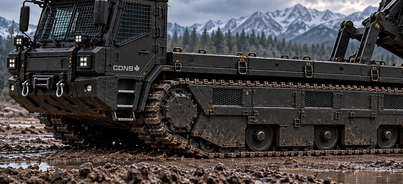
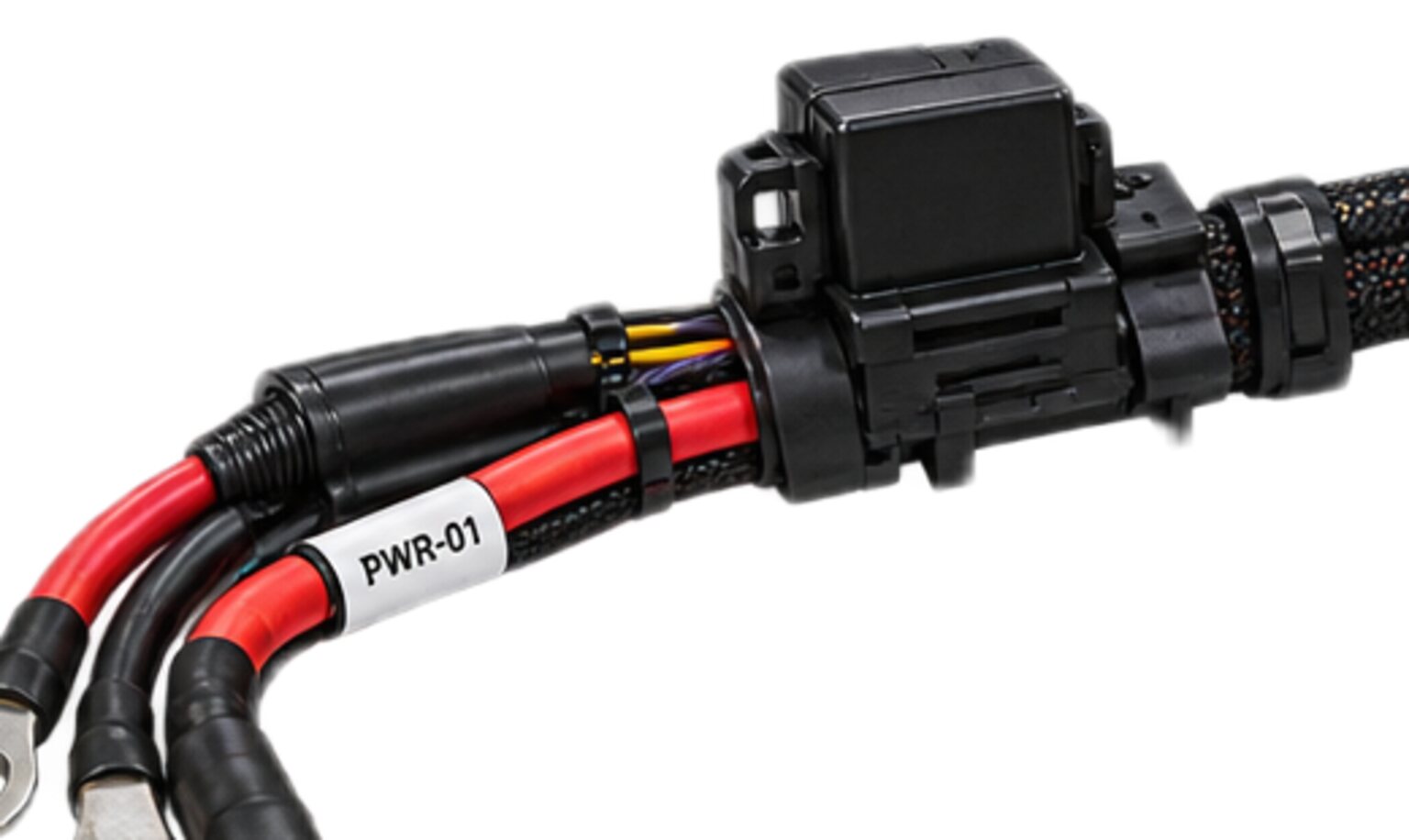
Safety circuits never share a bundle, a splice or a shell with power. On every loom this shop builds, the emergency stop chain, the guard interlocks, the enable switch and the safe-torque-off lines leave the safety controller as their own bundle, take their own route, pass the bulkhead through their own gland and land in their own shell. Power and data go other ways, and between the enclosure and the drive the three are strangers.
Every other circuit on the machine is designed to keep working. The safety chain is designed to fail correctly. A power feed that opens is a breakdown. A data bus that opens is a fault code. A safety chain that opens is a stop, and a stop is what the chain exists to deliver. It is the only circuit where a broken wire is the safe result and an unexpected voltage is the hazard, and every rule below follows from that inversion.
The seam
A safety chain has to reach every place a person can get at the machine and every place the machine can get at a person: the stop button on the operator station, the stop on the pendant, the switch on every guard and service hatch, the remote stop on a machine that runs with nobody in the seat. From those places it runs to whatever removes the energy: the contactor, the safe-torque-off input on the drive, the dump valve on the hydraulic circuit.
Those endpoints sit in the worst electrical neighbourhoods on the machine. The stop button shares a panel with the joystick, the display and the ignition feed. The safe-torque-off terminals are on the drive, beside the motor phases, and the two will arrive through one gland if nobody stops it. The safety chain has to go where power is thickest and data is densest, and arrive there without touching either.
That is the seam: a safety circuit, a power feed and a data bus that must reach the same places and must never touch on the way. A power conductor that chafes through onto a data pair corrupts a frame, and the bus retries. A power conductor that chafes through onto a safety input can hold the chain closed. The controller sees a healthy chain. The person holding the stop button gets nothing. That is the one fault the whole system exists to prevent, and it is why the safety chain gets its own copper rather than its own colour.
The topology
A stop chain is a loop. It leaves the safety controller on an output, passes through every stop device in turn and comes back to a safety input. Every device in the chain has a contact that is closed while the machine is allowed to run. Press any button, open any guard, and the loop breaks, and the controller drops its outputs. The outputs drive the contactors or the safe-torque-off inputs, and a feedback contact from each contactor returns to the controller, so that a welded contactor is seen the next time the chain is asked to close.
Where the machine's safety determination calls for redundancy, each safety function runs as a pair of channels, each its own loop through its own contact on each device, and the controller compares them. If one opens and the other does not, it declares a fault and stays stopped. The controller also puts a test pulse on each output, a brief dropout it expects to see arrive back on the matching input. A channel that returns a steady voltage where a pulse pattern was sent is being fed from somewhere it should not be. That is how the logic catches a cross-connection, and segregation is how the shop keeps it from ever having to.
The safety bundle branches only where a device sits, and that decides every split. Power branches where a load is. Data branches where a node is. The three families of bundle never branch at the same point and never share a breakout. Where a power branch and a safety branch both leave the trunk near the same bracket, they leave from opposite faces of it, on separate ties, and the drawing says so.
Inside the safety bundle the split is made at the device's own terminals: the loop enters the stop button on one conductor and leaves on another. There is no tee in the loom, because a tee is a splice.
Safety circuits never share a bundle, a splice or a shell with power.
The joint
There are no splices in a safety chain. Every conductor in the chain runs terminal to terminal, or terminal to contact, unbroken. A joint exists only where it can be seen, made with the specified tool, pull tested and reached with a meter. If a run is longer than any conductor we can get in one piece, the break belongs at a terminal or a connector on the drawing, and the drawing is changed.
- A splice fails in exactly the ways a safety chain cannot afford.
- It fails high, as the crimp relaxes or the strands corrode, and a high joint on a monitored input is an intermittent stop.
- It fails closed, as a stray strand works across under the sleeve, and a closed fault between channels is a bridge the controller may or may not see.
- It fails invisibly, because a splice under heat shrink cannot be inspected without cutting it open.
- And the label at one end of a spliced run proves nothing about the other end.
- Every conductor carries its circuit identity, end to end, and a splice is the point where that stops being true.
The joints that remain have to survive the machine. Vibration from an engine and a hydraulic pump through a frame that rings. Flex at the pendant, on a cable a person carries, coils, drops in the mud and drives over. Temperature swing, from a cold start on a prairie morning to an engine bay in August. Wash-down from a pressure wand held by someone in a hurry. A person pulling on the cable instead of the shell, or mating the connector in the dark with gloves on. Every one of those is a way for a joint to open, and an open joint is a stop. What the design cannot accept is a way for a joint to close onto something else.
That is why contact retention matters more in a safety shell than anywhere else. A contact that was not fully seated backs out under vibration and finds its neighbour. So every contact is seated and pulled to confirm retention before the shell is closed, and every cavity with no conductor in it gets a sealing plug, not air.
The interface
A connector is where segregation is decided by geometry. Inside the insert, contacts sit in cavities a fixed pitch apart, and a fixed pitch is a distance a fault can cross. A drop of salt water, a metal fine from a panel drilled after the loom went in, a pin bent on a blind mating: each bridges two adjacent cavities. If one cavity is a power contact and the other is a safety input, the bridge feeds the input with a voltage that says closed, and the controller believes it.
The first defence is the rule already stated: safety never shares a shell with power, so no cavity beside a safety contact can carry power. The second is contact zoning inside the safety shell itself, because the supply that feeds the stop devices and the controller's pulsed outputs are in there too, and a bridge from a supply cavity to an input cavity is still a false closed.
Zoning sets the cavity map so that every bridge you can draw between two neighbours produces a stop. An input is never adjacent to the supply that feeds its own loop. Where the insert has room, an input is bracketed by cavities that carry the safety common or nothing at all: a bridge to common pulls the input low and reads as open, which is a stop, and a bridge to an empty, plugged cavity does nothing. A bridge from one channel to the other carries the wrong pulse pattern and the controller catches it, but the map keeps the channels apart anyway. Geometry and logic back each other up, and neither is asked to work alone.
Three states of the chain have to read as safe, and each shapes the design. An open circuit reads as safe because the chain is closed to run. That is what makes the stop devices positive opening: pressing the button pulls the contact apart through a rigid link, so that a welded contact is still torn open by the hand. It is also what makes a broken wire a stop.
A de-energised circuit reads as safe because the chain is energised to run. Lose the safety supply, lose the controller, lose the whole electrical system, and every contactor releases. The chain is never wired so that a voltage is needed to stop.
A short circuit is the hard one, because a short to a live conductor is the one fault that can hold the chain closed against the operator. The logic handles part of it with pulses and paired channels. The rest can only be handled by where the copper is. A live conductor that is never in the same bundle, gland or shell as a safety conductor has no way to reach it. The first two states are settled by the circuit. The third is settled by nothing but segregation.
Each side of the interface promises the other something. The design authority for the machine promises the safety determination for each function, the device list, the channel architecture, the pulse scheme, the shell and the cavity map. The shop promises that each conductor is unbroken and carries its circuit identity, end to end, that the shell holds safety and nothing else, that the cavities are populated to the map and the empty ones plugged, that the safety bundle runs its own marked route, and that the finished assembly is checked for continuity and isolation before it leaves. An isolation test asks whether two circuits that must never meet are in fact separate, and it is run on every finished assembly. What the test proves is on test and acceptance.
When one side changes, the other does not improvise. A stop device added to a machine changes the loop, the cavity map and the label set, and the shop does not add it by opening the loom and splicing in a branch. The drawing is revised and the loom is built to the new drawing. Nothing is fabricated until the drawing is signed, and on the safety chain that rule has teeth. Where the chain belongs to a customer's machine programme, that programme owns the design and the drawing master. We build to a customer's issued set and we return the manufacturing detail: the cut list, the cavity population, the label set, the test record. We do not hold the design authority for a safety function.
CSA governs, and where the Canadian Electrical Code reaches the assembly the bench keeps circuits of different classes apart in shared enclosures and raceways unless a barrier separates them. The same principle holds inside a loom whether or not the Code reaches the machine, and where a finished assembly sits for approval is set out under CSA and the Code.
Through the route
Segregation is easy at the two ends and hard in the middle. Between the enclosure and the device there is a machine with one obvious path for wire, and everyone who ever added a circuit to it used that path. The safety bundle does not. It has its own route on the drawing, its own clamps and its own ties from the first clamp to the last. The general discipline is on routing; this is the part of it that safety adds.
Where the safety route has to cross a power route, it crosses at right angles, at a clamp, not in a loose lay. Two bundles that cross loose will lie against each other by the end of the first shift and chafe through by the end of the season. Where the two routes have to run parallel because the machine offers one chase, they run on opposite sides of it at the spacing on the drawing, and where the drawing calls for a barrier it goes in before either bundle is laid. The safety bundle is never laid inside a convoluted conduit shared with power, because inside a shared conduit there is no such thing as spacing.
Bulkheads are where every bundle wants to be in the same hole. A gland compresses whatever passes through it, and a chafe at a shared gland is a bridge with a clamp holding it together. The safety bundle passes the bulkhead through its own gland, with its own drip loop on the wet side. Where the bulkhead is crossed by a pass-through connector, the safety chain has its own shell on the panel, and if the panel was cut for one connector, it is cut for two.
Passages are where the machine moves against itself: a boom, a slewing joint, an articulation, a cab that tips, and on a machine with a removable operator station the link between the station and the chassis. Each is a length of loom that flexes for the life of the machine, and a bundle laced with another bundle wears through against it there. The safety bundle takes its own path through the passage, with its own strain relief at each end and its own service loop sized to the travel of the joint. Where the passage ends in a connector so the station can come off, that connector is a safety-only shell, and the design authority decides what the chain reads when the station is absent. If that calls for a jumper plug, the shop builds it as a keyed, labelled, lanyarded item that is on the drawing, and builds nothing of the kind that is not.
The covering of the safety bundle is marked along its length in a way that survives the machine, for the technician who opens it in a year and has to decide what to lace to what.
The failure
A segregation failure presents in one of three ways, and the first presents as nothing at all. A bridge between a live conductor and a safety input is silent. The machine runs, the guards open and close, the autonomy stack reports healthy, and nothing on the operator's side is any different. The chain is being held closed by a voltage that did not come from the controller, and the controller cannot know unless it was built to pulse and the pulses were built to be checked. It is found by a periodic test of every stop device, if the owner runs one properly, or by an operator pressing the button in earnest. The mechanism is almost always small. A chafe at a shared clamp. Water in a shared shell. A repair that laced the bundles together because they fit better that way. A field splice made to extend a run. A work light tapped from the spare conductor that turned out to be the safety supply.
The loud failure is the nuisance trip. A high joint on a monitored input, a corroded contact in an unsealed shell, one channel of a pair opening under vibration while the other holds. Each stops the machine for no reason anyone can see, worst in the cold and the wet and at full engine speed, and clears itself before anyone gets a meter on it. The operator learns to reset it. The reset becomes routine. Then one day the machine is needed and the trip will not clear, and somebody bridges the input out, just for today. Now the silent failure has been installed on purpose, by a person trying to get the work done, on a machine whose safety chain nobody trusts anymore. The nuisance trip is the road to the bypass, and every choice on this page that keeps joints out of the chain and contacts seated is a choice against that road.
The third failure looks like a software problem. A data pair laced with a drive output picks up the drive's switching noise, a sensor falls off the bus, and the autonomy stack takes the machine to a safe state, correctly, over and over, on a schedule nobody can predict. Everyone blames the software, and the software is fine. That is power against data rather than power against safety, caused by the same lacing, and the defences against it are on shielding and bonding.
None of these shows up on the bench, where the machine is still, dry and warm and the loom is new. A segregation failure arrives months in, on a working machine, in weather, as a symptom that points somewhere else. That is why the discipline is applied at build, where the loom can be seen, and not left to test, where it cannot.
The consequence
The first currency is a hazard. A stop chain that is held closed is a machine that will not stop when a person needs it to, and on an autonomous machine that person may be the only one there. Everything after that is money, and the money is real, but it is second.
The second currency is a truck roll to ground that has no labour. Someone drives, or flies, with a meter and a guess, to find an intermittent on a machine that was working when they left. A fault that clears when the engine is off exists only while the engine is running, so the machine has to be made to misbehave before it can be measured.
The third currency is rework, and rework on a loom is worse than the loom. A safety chain that has to come out of a finished machine is rebuilt with the field's tools, in the field's weather, by whoever is there. The field rebuild is the one most likely to carry a splice, because a splice is what you make when the reel is in the truck and the machine is in the yard.
The fourth currency is the record. When a segregation failure has hurt someone, the question that follows is what was drawn, what was built and what was tested, and by whom. A loom whose cavity map is on the drawing, whose conductors carry their identity end to end and whose isolation test is on the record gives that question a paper answer. A loom without those gives it somebody's memory. Who pays follows the order of the currencies: the operator first, then the owner in downtime, then whoever built the loom in rework, and then in reputation.
The air line
You already own this rule. It is on every tractor-trailer on the highway. The trailer's brakes are held off by air pressure. Break the line, and the brakes come on. Lose the compressor, and the brakes come on. Nobody has to decide to stop the trailer. Stopping is what it does when nothing is holding it back, and it takes air, deliberately applied, to let it roll.
- That is a safety chain.
- Open reads as safe, because the brakes apply when the line breaks.
- De-energised reads as safe, because the brakes apply when the air is gone.
- The one fault the design cannot reason its way out of is air arriving where it should not, holding the brakes off when the driver has asked for them.
- That is why the supply line and the service line are separate hoses, coloured differently and coupled separately, so a driver can tell them apart before the air goes on.
- That is a short circuit reading as safe, and it is done not with a valve but by keeping the two lines apart.
Everything on this page is the same rule in copper. The chain is held closed to run, anything that breaks it stops the machine, and the one thing that could hold it closed against the operator is kept in a different bundle, gland and shell so that it has no way to get there.
What we refuse
We do not put a safety conductor in a bundle with power. Not for a short run, not to fit a gland, not because the machine has one chase. If the machine offers one path, the drawing finds a second.
We do not splice a safety chain. If a run cannot be made in one piece, the break belongs at a terminal or a connector on the drawing, and we send the question back. A chain that comes in from the field with a splice in it is rebuilt without one, or not by us.
We do not put a safety contact in a shell with power. Spare cavities in a power shell stay empty and plugged. Spare cavities in a safety shell stay empty and plugged. A shell is one thing or the other.
We do not originate the cavity map for a safety shell. We transcribe the one the design authority for the machine issued. If the map we are issued puts an input beside the supply that feeds it, we say so before we build it, and we build it when the map is corrected.
We do not make a bypass, a jumper plug or a test lead that is not on the signed drawing. The ones that are on it are keyed to one socket, labelled so they cannot pass for a working connector, and lanyarded so they cannot be left in.
We do not apply a test value to a class of assembly. The isolation test on your loom is set on your loom, by the engineer responsible for it. A value nobody measured never reaches a wire, and a value nobody stated never reaches a test.
We do not call a circuit a safety circuit because it has a red button on it. If it does not read safe on open, on short and on dead, it is a control circuit with a red button, and we build it as one and say so in writing first. The button is not the safety. The chain is, and the chain is only as safe as the bundle it does not share.