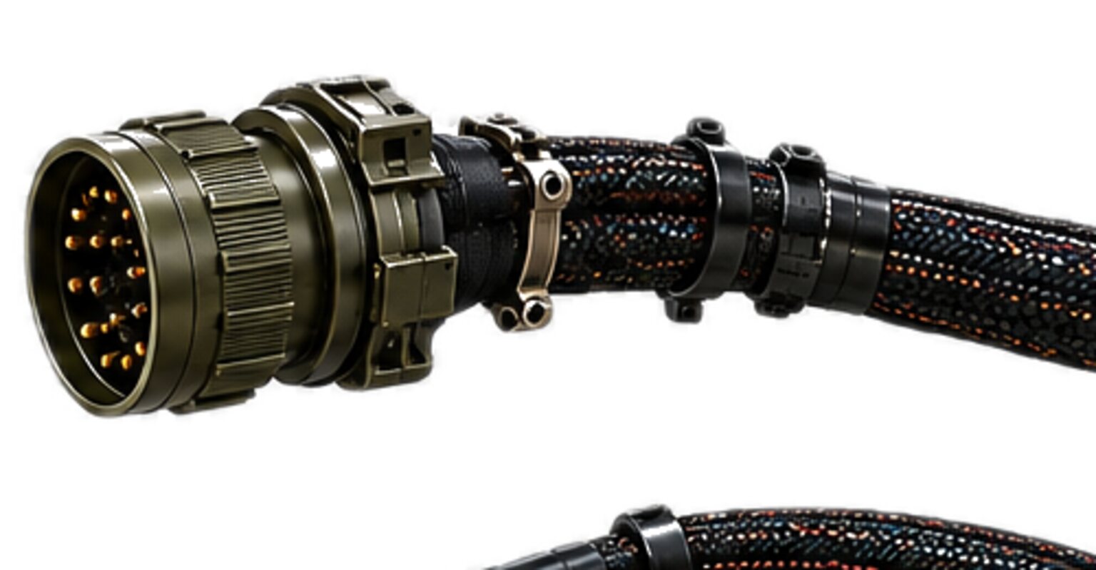
A shield is a conductor. It is the one conductor on a harness that nobody draws a circuit for, and it is the one that most often ends up carrying current nobody designed. Every shield has two ends. Each end is a decision, and the decision is made on the drawing before the cable is cut.
Bonding is the other half of the discipline, and it is a different thing from grounding. Grounding is a decision about what a conductor is referenced to. Bonding is a fact about whether two pieces of metal are touching. A machine bolted to a carrier is bonded whether anyone intended it or not, and a harness that does not account for that is built for a machine that does not exist.
The seam
The seam here is where the wanted meets the unwanted inside the same bundle. An encoder's pulse train, a level sensor's small analogue output and a fieldbus pair run in a loom that also carries a motor drive's switching edges, a contactor coil collapsing when the machine stops, a radio keying on and off, and a starter feed returning its current through the frame. They share a bundle, a bulkhead and a chassis, and the signal has to arrive readable anyway.
Every signal is twisted with its own return. Not with a return borrowed from the next circuit over, not with chassis, and not with the shield. A signal and its return twisted together occupy, on average, the same place in whatever field the pair passes through, so the field induces the same voltage in both, and a receiver that reads the difference between them reads nothing of the field. The twist also keeps the area between the two conductors small, and area is what a magnetic field couples into. A signal that returns through chassis has a loop the size of the machine, and a loop the size of the machine picks up everything the machine does.
The shield is the second measure, and it has limits a person who builds looms already knows. A copper braid stops an electric field. It does very little for a magnetic field at low frequency, which is the field a battery cable makes when the starter turns; distance and twist stop that, and the designer is choosing which of the two is available on each branch. At high frequency a shield stops magnetic coupling as well, but only when current can flow along it, and current can only flow along it when both ends are connected to something. That one fact is why the question of where a shield is grounded has two right answers.
A shield is not a substitute for segregation. Safety circuits never share a bundle, a splice or a shell with power, and a shield on a safety line is never offered as the reason two things that must never meet can be routed together.
The topology
A shield is drawn. It has an identity on the drawing like every other conductor, it is carried end to end, and at each end the drawing states what it lands on, or that it lands on nothing. Every conductor carries its circuit identity, end to end, and a shield is a conductor. A shield that fades out at a splice, or is assumed to pick up on the far side of a connector, is a piece of braid that happens to be in the cable.
Where a shield is grounded is decided by what it has to stop and by what sits at each end.
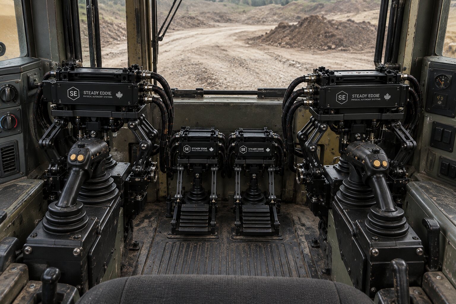
A shield over a low-level analogue line, a thermocouple, a strain bridge, a pressure sensor's slow output, is doing electrostatic work. It intercepts the electric field from the drive cable beside it and drains that charge to ground. Draining needs one path, and one is what it gets: the end where the signal is read, at the logger or the controller, because that is the reference the reading is made against. The far end floats, on purpose, and is finished so that it stays floating.
Ground that shield at both ends and it becomes a conductor tied between two points on the machine that are not at the same potential. Frame is not a perfect conductor. The starter return, the drive return and the lighting return all flow through it, and each flow makes a voltage between one end of the machine and the other. Tie a shield across that voltage and the shield carries a share of the current, and a shield carrying current puts a voltage along its own length that appears on the conductors inside it. The shield that was supposed to keep noise out is now the thing bringing it in. Two ends on the wrong shield, and you have made a loop that carries current nobody designed.
A shield over a fast data pair, a fieldbus, a camera link, an encoder line with sharp edges, is doing a different job. The noise it has to stop lives at frequencies where a shield grounded at one end only is a stub, and a stub of the wrong length is an antenna. That shield is terminated at both ends, to chassis, with full-circumference termination, so that the current induced on it can flow and cancel the field inside. The loop this makes is the same loop as before, managed instead of avoided: the chassis at both ends is bonded well enough that the frame carries the low-frequency current and the shield carries almost none of it. Where the two ends cannot be bonded well, the drawing shows one end bonded hard and the other bonded through a capacitor that blocks the slow current and passes the fast, and it names that component where it appears.
A shield is never used as a return conductor. Its job is to carry noise current away, and if the signal's return rides on it too, every bit of noise current it collects makes a voltage drop along it that is in series with the signal. The signal also loses its twisted partner, and its return now ends wherever the shield ends. A coaxial line is not an exception. Its outer conductor is a return by design, sized and terminated as one, and drawn as a circuit conductor.
Every conductor carries its circuit identity, end to end.
The joint
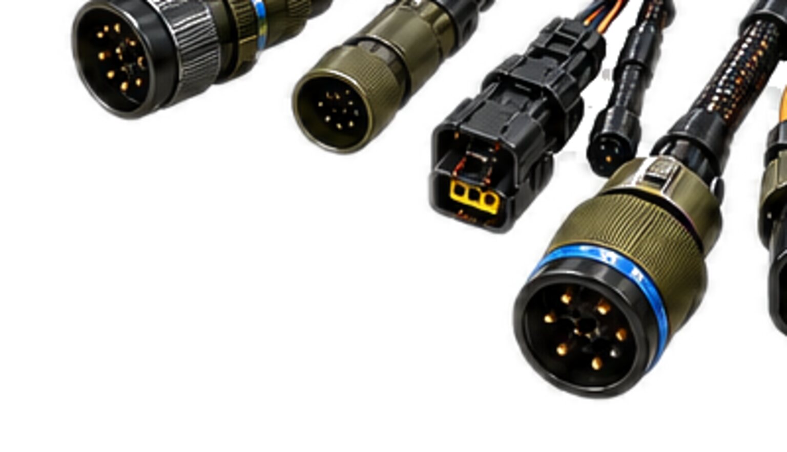
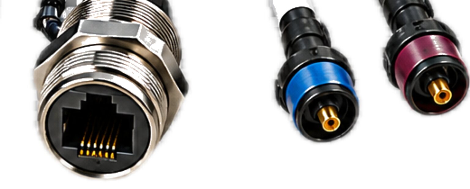
A shield ends where the harness enters a connector, and there are two ways to end it.
- The first is a pigtail.
- The braid is gathered, twisted into a tail or joined to a drain wire, and taken to a pin or a lug.
- The second is full-circumference termination.
- The braid is folded back over a ferrule or captured under a ring inside the backshell so that it touches the shell all the way around; the shell touches the receptacle shell all the way around when mated; and the receptacle is bonded to the panel it is mounted through.
- The braid stays a tube from the cable to the shell.
The difference is not tidiness. A pigtail is a length of single wire, and a length of single wire has inductance. At the frequencies where a shield on a data pair has to work, that inductance is an impedance, and all the noise current the whole cable's shield collected has to push through it on the way to ground. The voltage that builds across the pigtail lifts the entire shield away from chassis, and a lifted shield is no longer a wall. It is a wire driven at a voltage, and it radiates. The pigtail itself is a length of wire standing in free air beside the signal pins, which is the definition of an antenna and the worst place to put one. A pigtail is a fine conductor at low frequency, so it is acceptable on a slow analogue shield that lands on a pin and useless on a fast one that has to reach chassis. Full-circumference termination has no length to speak of and no loop.
Where a drawing calls for a shield to end on a pin, the shop builds it that way, and the tail is kept as short as the connector allows. Where a drawing calls for a backshell termination, no part of the shield passes through the connector face, because a shield brought onto a pin carries the noise inside the shell.
The joint has to survive the life of the machine, and the termination is chosen with that in mind.
Vibration. A braid captured under a clamp survives it, because the clamp takes the load and the strands stay soft. Solder wicks up into the braid and makes a hard point, and the strands break at the edge of the hard point, one at a time, over months. Solder is not banned. Solder at a place that moves is.
Flex. The strain relief takes the pull, the bend and the twist, and the termination sits inside it and sees none of them. A shield is not a strain member, and a backshell whose clamp holds the braid is asking it to be one.
Wash-down and weather. Water wicks along a braid under the jacket by capillary action, and if the backshell is not sealed the braid corrodes from the inside. A corroded braid reads continuous on a meter and is a poor conductor at frequency, which is a fault the meter cannot see. A shield that lives outside is terminated in a shell that seals.
A person mating it in the dark with gloves on. Full-circumference termination is done once, in the shop, inside the backshell. What the person in the field makes is the shell-to-shell contact, and a keyed coupling makes that contact whether they can see it or not. A pigtail landed under a screw by a person with cold hands is a termination that gets made differently every time.
A shield that floats at one end is finished at that end: cut back, covered under shrink and kept clear of the shell, so that it floats because it was made to, and not only until the first time the backshell is tightened.
The rest of what the connector has to be is on the connectors page.
The interface
A shield strategy is a system decision, not a harness decision, and it is carried out at an interface where each side promises the other something.
The harness promises that every shield is continuous between the points named on the drawing; that it is terminated the way the drawing says at each end; that it touches the shell, or does not, as drawn; and that the shell touches the receptacle shell when mated. It promises that a floating end floats, that a grounded end grounds, and that no shield carries a return.
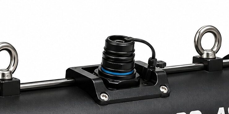
The machine promises the rest. The receptacle is mounted through a bonded panel, not a painted one. The chassis at each end of a double-ended shield is bonded well enough that the frame carries the low-frequency current. The equipment at each end treats the shield the way the harness expects. That last promise breaks most often, because a great many sensors tie their case to the cable shield inside the housing. Mount that sensor on bare metal and its shield is grounded at the sensor end through the mounting screws. A shield drawn single-ended at the logger is now double-ended, the loop exists, and nobody drew it.
When one side changes, the shield strategy changes with it, silently. A sensor is swapped for one whose case is tied to its shield. A bare bracket is painted at a rebuild. None of these touch the harness, and every one of them changes what its shields are connected to. The shield strategy belongs on the machine's drawing master because that is the one place that sees both sides.
At a payload-to-carrier seam the interface specification says which side grounds each shield, because a payload that grounds a shield the carrier also grounds has made a loop across the seam, through a latch and a rail, that opens and closes every time the payload is fitted.
Where a machine belongs to a customer's machine programme, that programme owns the design and the drawing master, and the shield strategy on it. We build to the customer's issued set and we return the manufacturing detail. A shield we cannot terminate as drawn, because the connector has no backshell provision or the drain has nowhere to land, goes back as a query, not out the door as a shop deviation. Nothing is fabricated until the drawing is signed.
Bonding
Bonding is metal touching metal. It is the electrical continuity between two conductive parts, and it exists when a clean enough surface is pressed against another with enough force that current can pass between them. That is all it is. It is a mechanical fact.
Grounding is the decision to connect bonded metal to a reference: earth, battery negative, chassis. A thing can be bonded and not grounded, which is a payload sitting on a bench with all its parts touching. A thing can be grounded and not bonded, which is a ground strap landed on a painted bracket. The reference reaches the strap and stops.
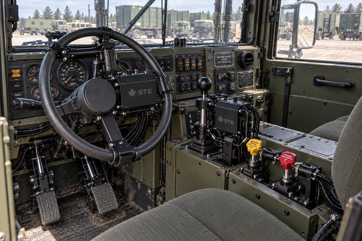
A machine bolted to a carrier is bonded whether anyone intended it or not. The mounting bolts, the bracket, the hinge pin, the rail, the payload latch and the sensor's mounting screws are all metal touching metal, every one of them is a bond, and every one of them carries current the moment there is a potential difference across it. Bonding is not a thing you add to a machine. It is a thing the machine already has, in whatever state the assembly left it, and the designed bond exists to give the current a better path than the accidental ones.
That is the rule for a bond conductor. It has to be a better path than the bearing, the hinge pin or the sensor screw. If it is worse, because it was landed on paint or its washer has corroded, the current takes the accidental path. A bearing that carries current pits its races. A sensor whose mounting screws are the ground return for a motor drive reads the drive's current as signal. A hinge pin that carries the frame bond opens every time the boom lifts.
- A bond conductor is drawn, sized, identified and terminated like any other conductor, and its landing is prepared.
- Paint is an insulator.
- Anodize is an insulator.
- Powder coat is an insulator.
- A bond landed on any of them is a capacitor, and a capacitor passes the fast current and blocks the slow, so that bond reads open on the meter and will not carry a fault current the day it is asked to.
- The surface under a bond is taken to bare metal, the lug lands with a serrated washer under a marked fastener tightened to the value on the drawing, and the finished joint is coated so that the bare metal does not corrode.
- A bond between dissimilar metals is a galvanic cell waiting for moisture, and the lug and washer are chosen to match the surface.
- A corroded bond is worse than an open one.
- An open one is found.
- A corroded one is intermittent.
On the capture rig of a training system the bonding question is turned inside out. The instrumentation loom is grounded to its own battery negative and to nothing on the host machine. That is a design intention, and bonding does not care about intentions. If the rig's bracket sits on bare frame, the rig is bonded to the machine through the bracket, and the shield that was grounded at the logger is grounded at the frame as well. The rig is isolated at its mounts on purpose, and that isolation is measured as an absence: a continuity check from the rig to the host harness returns nothing. An instrument that touches the machine has changed the thing it was measuring.
On a plant or remote-site package the bonding scheme is not the harness builder's to invent. CSA governs, the Canadian Electrical Code governs bonding in a fixed installation, and the pre-wired enclosure, the skid and the interconnect are built to the scheme the drawing shows under that Code. Where a finished assembly sits for approval is set out under CSA and the Code.
The failure
A bad shield termination does not show at the bench. The assembly passes continuity, because the pigtail conducts. It passes isolation, because the shield is not touching a signal conductor. Everything the bench can ask, the harness answers correctly. The bench does not have the machine's noise, and noise is the only thing the termination was for.
It shows in service, and it shows when things coincide. The drive is under load and the boom is at the end of travel and the radio keys. The machine has cold-soaked overnight and the braid has drawn back inside the jacket. The solder joint at the base of a pigtail has been vibrating for a season and has just parted its last strands. Each of those is a day, not a bench.
How it presents is what you have already lived through. An encoder loses counts when the drive runs and never when it idles, and the drift is blamed on the mechanism. A fieldbus logs errors under load and is clean at rest. A camera link drops frames while the transmitter is keyed, on a payload that ran perfectly on the bench. A safety input reports a fault on a chain that has not opened, and the machine stops for no reason anyone can find. None of these repeat on demand. All of them repeat eventually.
A ground loop presents differently. Hum or drift on an analogue line that tracks whatever else the machine is doing. A shield that is warm. In the extreme case, a shield that has become the machine's ground strap: the frame bond has gone open, the shield is the next best path between the two ends, and starter return current goes down a braid built to carry almost nothing. That shield is found by smell.
A bad bond presents last and worst. It is a corroded surface that touches on some days and not on others, so the machine passes every check at the shop, fails on the pad, and passes again when it comes back. A bond that opens across a moving joint opens with the motion, and the fault is filed against whatever the machine was doing at that moment.
When it shows is the useful fact. At commissioning if you are lucky. The first time three things coincide if you are not. Never at the bench, and never twice in a row for the person sent to find it.
The consequence
Who pays is the person who has to chase it. A bad termination costs almost nothing in parts and a great deal in attention, spent on a machine that has to be stopped to be opened, that does not show the fault when stopped, and that is somewhere other than the shop. The currency is truck rolls, downtime, and the credibility of everyone who said the harness was fine, which it was, at the bench.
On an autonomous machine the consequence has a sharper edge. A noisy safety input trips when it should not, and an operator who has learned to reset the trip has learned to ignore it. A payload works in the hand and fails in the air, on a carrier that is not coming back to let you look. Every one of those is the part of the system that cannot be corrected in software after it ships, and every one of them was decided at the two ends of a shield before the cable was cut. The test and acceptance page says what the bench can prove about a shield and a bond, and what it cannot.
The eavestrough
A shield is an eavestrough. It collects everything that lands on the roof and carries it away from the wall the roof was built to keep dry. It works only if it drains somewhere.
A pigtail is a full-width trough that ends in a downspout the width of a pencil. In a drizzle it keeps up. In a storm the trough overflows, and the water lands exactly where the trough was meant to keep it from landing. Full-circumference termination is a downspout as wide as the trough, and the storm goes where it was sent.
Two downspouts at two ends, into two drains that are not at the same level and are joined underneath, and the trough is a channel. Water runs through it from one drain to the other along the wall, on a dry day, carrying water that never fell on the roof. That is the loop, and that is the current nobody designed.
What we refuse
We refuse to use a shield as a return conductor. A shield has one job, and a return is not it.
We refuse to substitute a pigtail for a full-circumference termination, or the reverse, without the drawing changing first. The drawing chose the termination for the frequency the shield has to work at.
We refuse to ground an end the drawing leaves floating, and we refuse to leave floating an end the drawing grounds.
We refuse to guess when the drawing is silent. A shield with no termination shown at one end is a query, not a default. Nothing is fabricated until the drawing is signed, and a shield is fabricated.
We refuse to land a bond on paint, on anodize, on powder coat or on corrosion, and we refuse to call a strap on a painted bracket a bond.
We refuse to solder a braid at a place that flexes, and we refuse to hold a cable by its shield.
We refuse to publish a transfer impedance, a bond resistance or a shield continuity limit for a class of assembly. Those values belong to a specific assembly, measured by the engineer responsible for it against that assembly's own specification. A value nobody measured never reaches a wire, and it does not reach this page either.