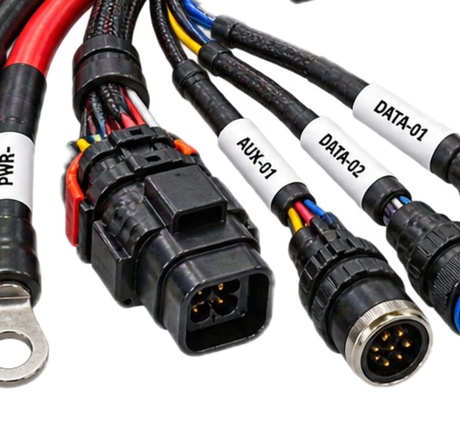
Everything a payload has to say to its carrier, and everything the carrier says back, travels on this harness. It is the lightest conductor set at the interface and the one judged most harshly. A feed slightly wrong still carries power and a bond slightly wrong still holds, but a bus slightly wrong drops a frame, and a frame dropped at the wrong moment is a payload the carrier can no longer see. It is built beside a feed that switches under load, so it is engineered as one part of a matched set and not as a cable.
The mechanism
This harness is a set of twisted pairs under a shield. Each signal the interface defines travels on a pair, the two conductors carrying it against each other, twisted together at a lay held for the whole run, on one cable construction from end to end. A signal that borrows another signal's partner, or that uses the shield or the structure to complete itself, is not on a pair. It is on a loop, and the loop is what picks up the feed.
Around the pairs sits a shield, continuous from backshell to backshell through every connector in the run. A shield that stops at a connector body and starts again on the other side is two shields with a gap at the one place where the noise is. Where the interface calls for each pair to be shielded on its own as well, each pair has its own shield under the overall one, and the two are terminated separately, as the drawing says. The shield is a conductor with one job: it is not the return of any pair, it is not the bond between payload and carrier, and it is grounded nowhere except where the interface says.
At each end the shield is terminated round its full circumference into the backshell, not gathered into a drain wire and put under a screw. A drain wire is a single wire standing in for a tube, and at the speeds a bus runs it is not the same thing. The pairs pass through the backshell into the shell with their twist held as close to the contact as the contact allows, and the untwisted length at each contact is a dimension on the drawing, because everything untwisted is unprotected by its partner.
The topology is whatever the interface owns. Between one payload and one carrier the bus is a line from shell to shell, terminated at each end as the interface says. Where the carrier runs a bus that several nodes share, this harness is one stub off it, and the stub's length is on the drawing, because a stub too long for its bus reflects part of every frame back into every other node's traffic. There is no splice in a data pair, and no branch the drawing does not draw.
What it is engineered to
The interface promises in both directions. The carrier promises a reference for the pairs, a point where the shield is grounded, a termination at its end, and a bus quiet enough to carry the traffic it asks for. The payload promises to drive the pairs in the form the interface defines, to present a defined state when it is unpowered, and to draw nothing through its bus lines when its feed is off.
Matched along its length means that a signal edge meets the same geometry at every point of the pair. Flick a rope tied to a post and the wave comes back at you from the post. Everywhere a pair changes, at a tight bend, a splice, a crushed length under a clamp or an untwisted run at a contact, part of every edge comes back the same way, and the receiver reads the edge and its reflections together. That is a bit read wrong, and it reads wrong only at speed and only on the frames whose timing lands on it, so the bench never sees it. So the harness holds the geometry: no tie is pulled tight enough to change the pair's shape under it, the two conductors of a pair are cut to the same length so their edges arrive together, and nothing is spliced.
Grounded where the interface says and nowhere else is a decision the interface owns. Grounded at one end, the shield stands against a field. Grounded at both ends, it also carries whatever current the two grounds disagree by, and on a carrier where a feed's return or a motor's return has put those grounds at different points, that current runs along the shield beside the pairs. Whichever the interface chooses, the harness makes true, and it adds no third ground of its own: no backshell resting on a bracket, no clamp biting through the jacket into the braid.
The defined unpowered state is the payload's promise, and the harness carries it. When the payload's feed is off the carrier still sees the bus, and what it sees has to be what the interface defines: the pairs at their idle state, terminated or open as the interface says, drawing nothing. A payload whose bus lines find a path through its own unpowered protection turns its data pairs into a feed nobody drew, and a payload that pulls a shared bus to one state when it is unpowered silences every other node on it. The harness adds no path of its own to what the payload presents.
The joint has to survive vibration first. A contact that moves against its mate by the smallest amount, on every cycle, wears through its plating and becomes an intermittent, so the shells are locked, the backshell takes the strain so the contacts carry none, and the bundle is tied down so the connector is not the thing that stops it moving. Then temperature swing, which stiffens the jacket and moves the geometry of a pair bent tighter than its drawing. Then condensation inside a shell mated cold. Then a person mating it in the dark with gloves on.
Every conductor carries its circuit identity, end to end.
The discipline applied to this harness
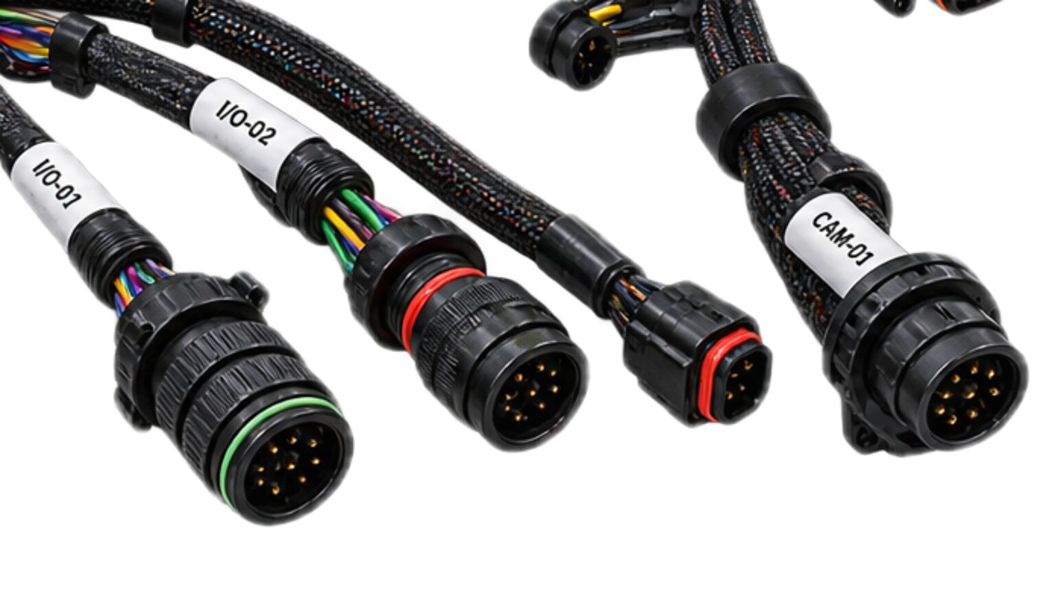
Every conductor carries its circuit identity, end to end. On a bus that sentence does more than label. Each pair is marked with its identity and its polarity at both ends and along the run, so a person at the carrier's shell can read which pair is which and which conductor is which without opening the bundle or lifting a contact.
Segregation keeps the bus out of the feed's bundle and out of the interlock's bundle. The bus runs in its own, at the spacing the formboard holds, crossing the feed at a right angle where it must cross and never running alongside it.
Shielding and bonding on this harness is the shield's continuity and its single, drawn ground. The termination is full-circumference at both ends. Where the interface grounds the shield at one end only, the shield's far termination is insulated from the shell it sits on, and that insulation is tested, because a shield grounded at one end on the drawing and at both ends on the machine is the usual way a bus that worked on the bench fails on the carrier.
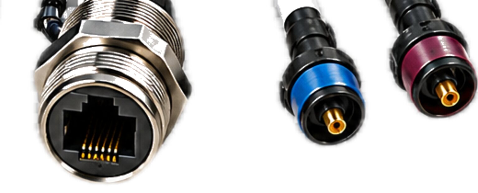
Connectors are keyed so the bus plug cannot be forced onto another receptacle, and the contacts are sized for the pair conductor and crimped with the tool for that contact. Routing is fixed by the walk and held by the formboard, and the bend at every fixed end is the drawing's bend, because a bend tighter than the lay allows is a reflection you did not draw.
Test asks three things of every finished assembly before it leaves. Continuity asks whether each conductor of each pair is one conductor from contact to contact, and whether the shield is one conductor from backshell to backshell. Isolation asks whether each pair is separate from every other pair, from the shield and from everything else in the set, and whether the shield's far termination is separate from its shell where the drawing says it must be. Polarity asks whether each conductor lands in the cavity the map assigns. What each is set to is stated on that assembly's own drawing by the engineer responsible for it, and the result goes into that assembly's own record.
Done badly, this harness fails in ways that look like software. A drain wire under a screw is a shield that is open at speed, so the bus drops frames whenever the feed switches or a motor starts. A shield grounded at both ends when the interface said one carries the carrier's ground current down the bundle, and the errors track the load. A spliced pair, or a pair crushed under a clamp, reflects, and the bus is clean at idle and bad under traffic.
A bus that drops traffic on one carrier and not another is found by ruling the harness in or out, then looking at the reference. The harness has a serial and a record that says what it was when it left: pairs of two conductors, a shield in one piece, isolation intact. Swap the harness between the two carriers. If the fault follows the harness, it is the harness, and its record and its labels say which pair to open first. If the fault stays with the carrier, the difference is in where that carrier grounds the shield, what its bond between payload and carrier is, how it terminates its end, and what it switches that the other carrier does not. That is a reference fault, and the reference is the subject of the ground and bond harness.
How it is bought
This harness is bought from an issued interface specification or drawing set. Nothing is fabricated until the drawing is signed. You send the specification that owns the interface, or the drawing set, and the shop performs the takeoff from it: pair, shield, jacket, shell, backshell, seal, contact, plug and marker, with their quantities. The components we specify carry their own certification. The approval route for a finished, project-specific assembly is confirmed with the certifying body for that assembly before it is built, and we tell you where yours sits before we build it, not after. CSA and the Canadian Electrical Code govern any assembly built for sale or installation in Canada.
The shop drawing carries the pairs and their polarity, the shield and where it is grounded, the termination at each end, the untwisted length at each contact, the bend at each fixed end, the marking and the tests, and it is signed by the engineer who owns the interface before anything is cut. Where the interface is silent on something the drawing needs, the silence goes back as a question, not a guess. A value nobody measured never reaches a wire.
The walk fixes the lengths, with the shells in hand on the carrier and the payload and the bend at each end in view. The formboard is built from the walk, and every assembly after the first is laid on the same board, so the geometry that matched on the first one matches on the last.
Each assembly leaves with its record: the serial, the lots of pair and shield that went into it, the crimp tool and its check, the result of each test on that assembly and who ran it. The manufacturing detail goes back to whoever owns the design. We build to your issued set and we return the manufacturing detail: the formboard, the cut list, the cavity map as built and the record, so the design owner holds the harness as built and not only as intended.
- We do not splice a data pair.
- We do not ground a shield where the interface did not say to.
- We do not terminate a shield with a drain wire under a screw because the backshell on hand does not take a full termination; the right backshell goes on the takeoff instead.
- And we do not quote a bus from a description of the traffic, because the interface that defines the pairs is where the drawing starts.
- Send it to enquiries.
- If you have only part of it, send that, and the reply is the list of what the drawing needs before it can be signed.