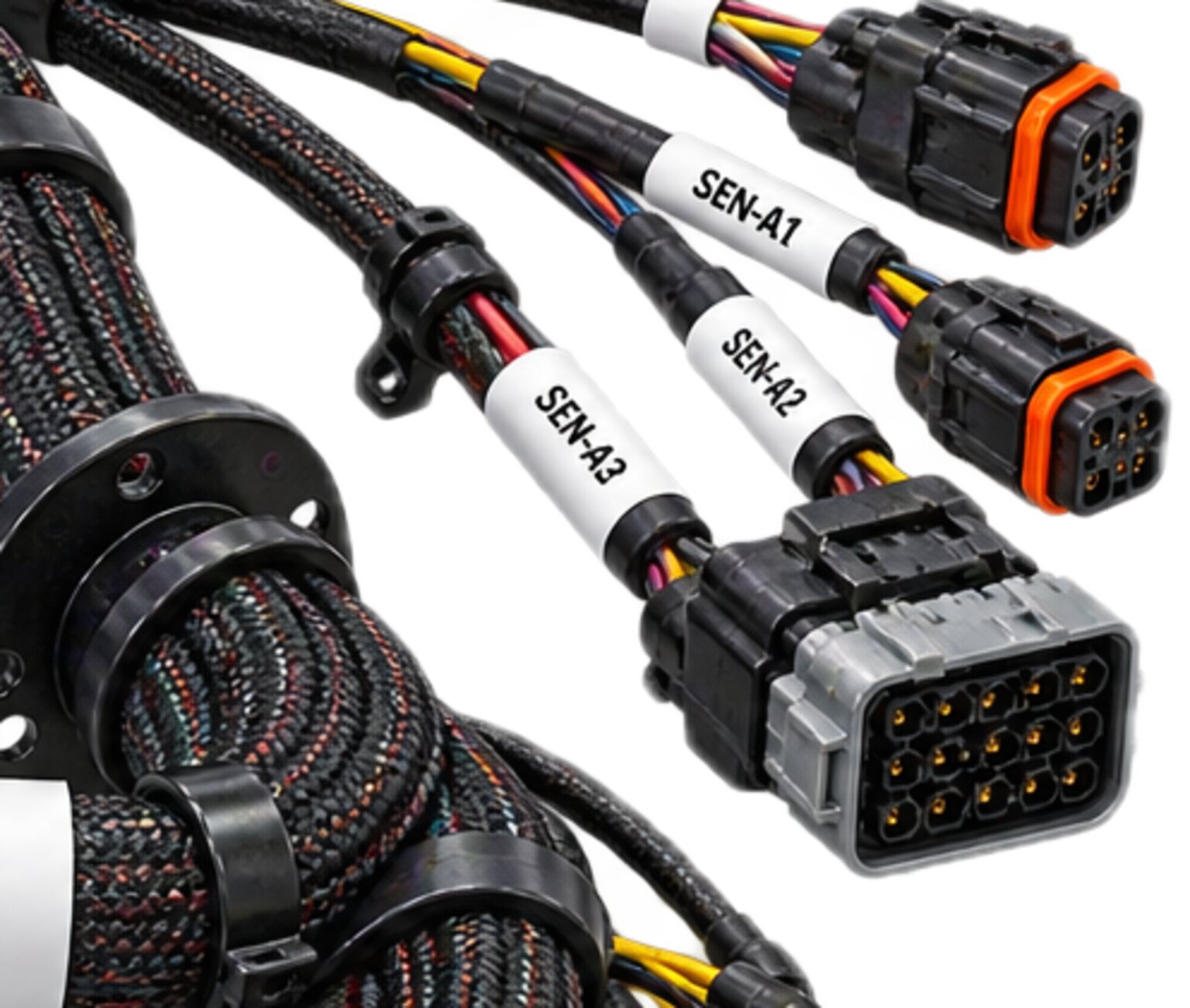

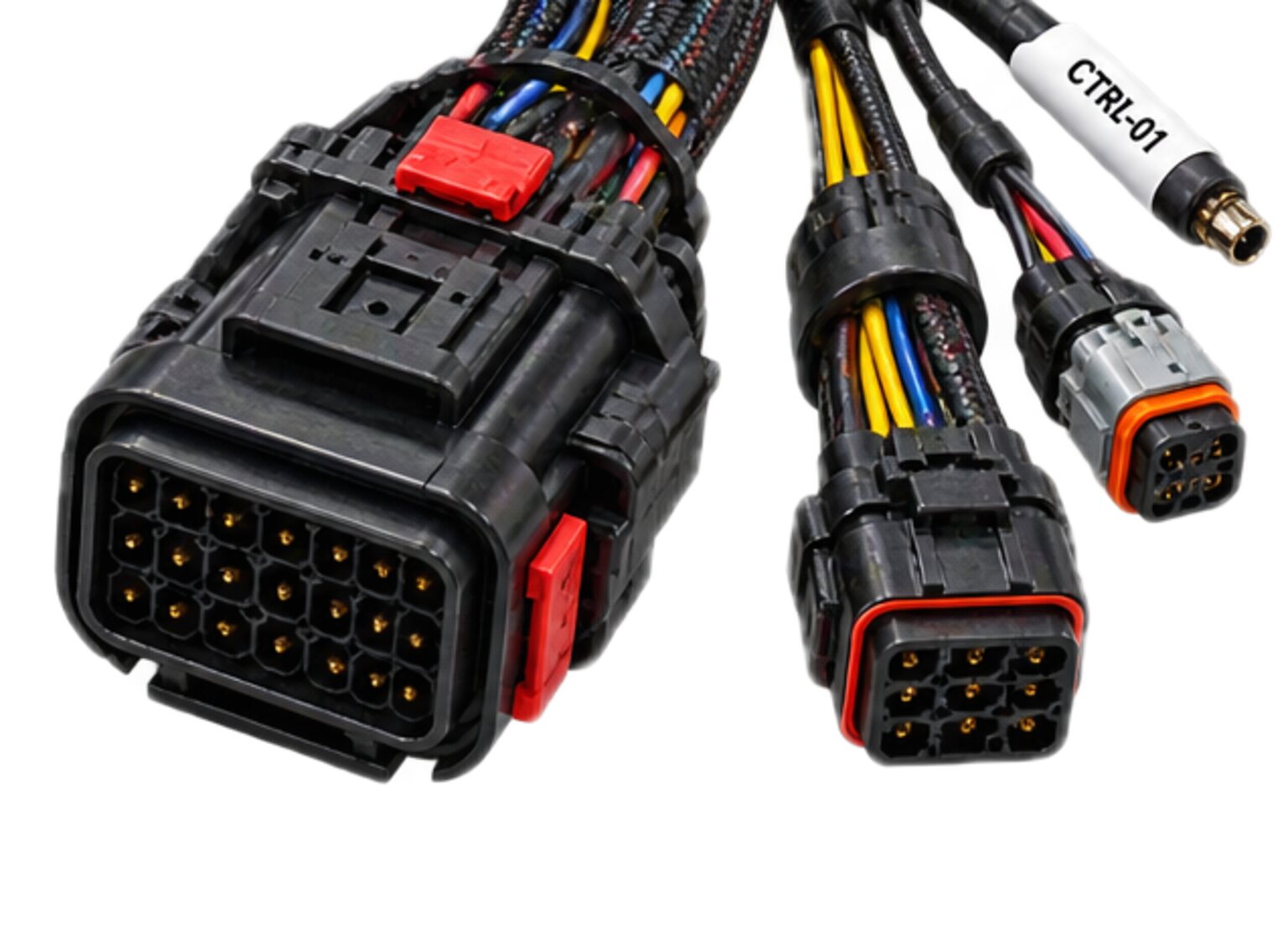
A harness comes off the formboard looking finished. Every conductor is where the board says it goes, every connector is closed, every label reads. None of that is proof. The board proves the harness was laid out to the drawing. The bench proves the harness is the drawing, conductor by conductor, in copper. Between the two sits the seam that matters here: the point where an assembly stops being the shop's opinion of itself and becomes a record.
The tests on the bench are questions with a yes or a no for an answer, asked of one specific assembly against that assembly's own specification. Each test proves one thing and is blind to the rest. That is why there are several, and why they run in an order. A test that is run before the one it depends on gives an answer that means nothing, and a shop that does not know which tests are blind to what will pass a harness that fails in the field.
One rule governs everything below. The value a test is set to is decided by the engineer responsible for that assembly, against that assembly's own specification, and it is written on that assembly's record. It is never stated for a class of assembly, and it is not stated here. What follows describes what each test proves. It does not describe what any test is set to, because a value nobody measured never reaches a wire.
The order
Every test on the bench assumes the one before it has passed. Continuity is first because every later test is meaningless on a circuit that is not connected. Isolation follows continuity because a conductor that goes nowhere is perfectly isolated from everything, and an isolation pass on an open circuit is a lie the bench will tell you if you let it. Bond follows isolation because a bond test deliberately proves a connection to ground, and you want to know the circuits were separate from each other and from the shield before you prove the shield to the shell. The keying proof is last because it needs the finished assembly, closed, clamped and labelled, and the drawing's key allocation is only realised at final assembly.
The crimp pull test sits outside this order. It is destructive. It cannot be run on the assembly's own crimps, and it cannot be run on a crimp that is already inside a shell. It runs at the crimp station, on samples from the run, before the assembly exists as an assembly. It is in the table because the bench relies on it: continuity cannot see a marginal crimp, and the pull test is the only thing that can.
| Test | What it proves | What it is blind to | When |
|---|---|---|---|
| Crimp pull | The tooling is making a joint that holds | Anything about the finished assembly | At the station, on samples, through the run |
| Continuity | The wire list is in the copper, pin to pin | Insulation, crimp strength, anything not in the list | First on the bench |
| Isolation | Circuits that must never meet are separate, under stress | Chafe that has not happened yet | After continuity |
| Bond | The ground path is metal, not paint or a strand | Whether the far end of the shield is open | After isolation |
| Keying | Every plug refuses every receptacle on the assembly but its own | Nothing electrical | Last, on the closed assembly |
A shop that runs these in another order is not running a different process. It is running fewer tests than it thinks.
Continuity
Continuity asks one question of every conductor in the wire list: does the pin at one end reach the pin at the other end, through every splice on the way, and nothing else? The second half of that question is the half that gets skipped. A conductor that reaches its pin and also reaches a neighbour's pin has passed the first half and failed the assembly. So the test walks the list both ways. Every conductor that should be connected is proven connected, and every pin that should be connected to nothing else is proven alone.
On an assembly with many connectors the bench does this through a fixture that mates to every connector at once and steps through the list. On a small assembly it is done pin by pin with a probe and the wire list, and the result is the same: a list of pairs asked and answered. What continuity proves is that the topology on the drawing is the topology in the loom. Where the bundle branches, where it splits, which conductor leaves at which breakout, all of that is in the wire list, and continuity is the list read back from the copper.
- What continuity is blind to matters more than what it proves.
- It cannot see the insulation.
- A conductor nicked at the strip passes.
- It cannot see the crimp.
- A terminal holding the wire by a few strands conducts perfectly at rest on a bench, and opens on the first cold morning under vibration.
- It cannot see the shield unless the shield's drain is in the wire list, which on any harness this shop builds it is.
- Continuity proves the harness is wired.
- It does not prove the harness is built.
Safety circuits never share a bundle, a splice or a shell with power.
Isolation
An isolation test asks whether two circuits that must never meet are in fact separate, and it is run on every finished assembly before it leaves. It is the electrical proof of the build rule that safety circuits never share a bundle, a splice or a shell with power. Separation is a build fact. The safety chain is in its own bundle, on its own connector, and it is that way because the drawing puts it there. The isolation test proves that the build fact survived the build. A strand of braid trapped in a backshell, a nick at a strip, a conductor pushed through the wrong grommet: any of these can undo on the bench what the drawing did on paper, and none of them shows up on continuity.
The test stresses the separation deliberately, because insulation weakened by a nick will hold at rest and fail on a surge, or hold dry and fail in the first wet week. The stress is applied between every circuit and every other circuit it must never meet, and between each circuit and the shield and the shell. How much stress, and for how long, is a decision the engineer responsible makes from that assembly's insulation system, its connector's own withstand rating and its drawing. That decision is on the record. It is not here.
Isolation is blind to what has not happened yet. It proves the separation as built. Whether the separation survives a bundle rubbing on a bracket in service is a question for the routing and the tie-down, not for the bench. The test proves the harness. It does not prove the installation.
Bond
A bond is a path the drawing intends. Shield to backshell, backshell to shell, shell to the receptacle's ground, or a strap from an enclosure to chassis. The bond test proves the path is metal all the way. It asks whether the connection reads like a piece of metal or like a joint, and a bond that reads like a joint is a bond made through anodise, through paint under a lug, through a lock washer that did not bite, or through a single strand of braid where the whole braid was meant to be captured. Each of those passes a visual. Each of those is a bond until the first fault current asks it to be one.
The bond test comes after isolation for a reason. A shield is grounded at one end only, or it is grounded at both ends, and the drawing says which. A shield grounded at one end is a shield against one thing. Ground both ends where the drawing did not ask for it, and you have built a loop carrying current nobody designed. So the bond test at the grounded end and the isolation test at the open end are the same shield being asked two different questions, and if isolation had not already been proven the bond test could not tell an intended ground from an accidental one. The order is the proof.
What bond is blind to is time. A bond through a fastener that is tight on the bench is a bond that depends on that fastener staying tight. That is why the drawing calls the fastener, the washer and the finish under it, and why the record names them.
The crimp pull test
The crimp is the joint. A crimp is a cold weld formed by a die at a set height on a terminal that matches the wire, capturing every strand at a strip length that leaves no strand short and no insulation in the barrel. When it is right it is stronger than the wire. When it is wrong nothing on the outside says so. A crimp with a fraction of the strands captured, or made on a die a size out, or made on a terminal from the wrong wire range, looks like every other crimp and conducts like every other crimp. The only way to know what a crimp is holding is to pull it until it lets go.
So the shop makes samples. At the start of a run, before any conductor for the assembly is terminated, a sample is crimped on the same tool, the same die, the same terminal lot and the same wire, and pulled in a fixture until something gives. What gives is the answer. If the wire breaks and the crimp is still holding the stub, the tooling is making a joint. If the terminal lets go of the wire before the wire lets go of itself, the tooling is not, and the run does not start. Through the run, further samples are made and pulled the same way, because a die wears, a setting drifts, and a terminal lot can change under a person's hand. How many samples, and how often, and the force at which a pull is judged, are set by the engineer responsible from the terminal maker's data for that terminal on that wire, and they are on the record. None of them is stated here.
A failed pull is a statement about the tool, not about the sample. Every crimp made on that setup since the last passing sample is suspect, and suspect means quarantined. The station stops. The die, the crimp height, the strip length and the terminal lot are checked. The suspect terminals are cut off and the conductors re-terminated on tooling that has passed a new sample. The record shows the stop, the cause and the re-termination. Nobody pulls a second sample to see whether the first was unlucky. A crimp that lets go on the bench is a crimp that lets go on the machine.
- The cost of a failed pull is why the samples are spaced through the run and not only at the start.
- A failure at setup costs a terminal, because nothing else has been crimped.
- A failure mid-run costs the quarantine back to the last pass.
- A failure with no sample since setup costs the whole run.
- Re-termination consumes conductor length.
- A takeoff that carries an allowance for it loses the allowance.
- A conductor cut to length with no allowance is scrap, and the whole conductor is re-cut, re-labelled and re-laid on the board.
- The pull test is cheap.
- Everything downstream of skipping it is not.
The keying proof
Connectors in a family look alike. The same shell size with the same insert arrangement is made in several key positions, so that a plug fits its own receptacle and refuses every other receptacle of the same size. On a harness with several connectors from one family the drawing assigns a key position to each, so that a person cannot mate a plug to the wrong receptacle even when trying to. The keying proof is where that assignment is proven on the finished assembly.
It is run last, and on the closed assembly, for a reason. A key position is realised at final assembly, to the allocation the drawing made, when the insert is clocked in the shell and the backshell is made up over it. A backshell that has been assembled can hide an insert that was rotated a position out, and everything electrical about that connector is still correct. Continuity passes. Isolation passes. Bond passes. The plug will not mate with its receptacle, or worse, it mates with the wrong one. So the proof is physical. Each plug on the assembly is offered to its intended receptacle and mates. Each plug is offered to every other receptacle of its size on the interface and refuses. Where a connector has a polarity rather than a key, it is offered reversed and refuses. The labels on the plug and on the receptacle agree with each other and with the drawing.
The proof is done the way the connector will be handled in service, and the harness has to pass by geometry. A person mating a payload in the dark with gloves on is not reading labels. The connector has to refuse the wrong receptacle in their hand. That is the interface promise: the harness side says which receptacle it fits, the receptacle side says which plugs it accepts, and if either side changes its keying without telling the other, a plug that mated last month mates with nothing. See connectors for how the key positions are chosen. The keying proof is where the choice is checked.
The record
- Every test on this page produces a line on the assembly's own record, and the record leaves with the harness.
- It carries the assembly's identity, the drawing and the revision it was built to, and the wire and terminal lots that went into it.
- It carries the crimp tooling, the pull-test samples, the results of each pull and any stop.
- It carries each bench test, the value it was set to, the engineer who set it, the technician who ran it, the result, and the date it was run.
- It carries the keying proof and any re-work, with what was re-worked and why.
- It is one document per assembly, and no two assemblies share one, because no two assemblies share a set of test results.
The record is found again by the harness. Every conductor carries its circuit identity, end to end, and the assembly carries its own identity on its label. That identity is the key into the record. A harness that comes back reads its own label, and its record is pulled without a search. A single conductor cut from a loom carries a circuit identity that maps to the wire list, and the wire list maps to the assembly, and the assembly maps to the record. The other direction works too. A terminal lot that is later found to be bad is traced through every record that names it to every assembly that carries it. What the record holds and how it is kept is described under the record, and the identity the harness carries is described under labelling and traceability. A harness without its record is a harness whose tests happened to someone's recollection.
Where a machine programme owns the design and the drawing master, the record goes back to it. We build to a customer's issued set and we return the manufacturing detail, and the test record is part of that detail. The record names the issued set it was built to, the test specification it was tested to, and who set any value the set did not carry. The programme holds the design authority for that harness. The record does not claim otherwise.
The value this page does not state
Every value a test is set to is decided on a specific assembly by the engineer responsible for it, against that assembly's own specification. It is written on that assembly's record and nowhere else. This page carries no test voltage, no current, no duration, no sample rate and no acceptance figure of any kind, and no other page on this site carries one either.
This is a refusal, not a caution. A value stated for a class of assembly is a value that nobody measured on your assembly. It was written by someone who had not seen your drawing, did not know your insulation system, had not read your connector's withstand rating and had no idea what your machine does when the safety chain opens.
Where a customer's issued set carries a test specification, the shop tests to it as written and records the values it carries. Where the set does not carry one, the engineer responsible writes the assembly's test specification from its components' own ratings and its service, and states every value on it. It goes to you before the build, so the criteria your assembly will be accepted against are agreed before any copper is cut. Nothing is fabricated until the drawing is signed, and the test specification is part of what is signed.
How an untested harness fails
An untested harness rarely fails at power-up. That is the problem with it. The faults the bench would have found are the faults that hide.
A miswire between two conductors that sit at the same potential in the machine's rest state survives the first switch-on and every switch-on after it, until the machine enters the state where those two conductors are supposed to differ. Then a motor runs the wrong way, or an interlock reads closed when it is open. A nicked conductor holds dry and fails in the first wet week, or holds at rest and fails on the first surge, and the fault reads as noise on a data bus that was fine yesterday. A marginal crimp conducts on the bench and opens under vibration when it is cold, closes again when it warms, and presents as an intermittent on a machine nobody can hold still long enough to find it. A bond through anodise reads as a bond until a fault current asks it to carry something, and then the shield floats and the bus goes deaf. An unkeyed plug mates with the wrong receptacle in the dark, and a payload that was supposed to draw from one feed draws from another.
Every one of those presents late, away from the shop, on a moving machine, as a fault that clears when a technician arrives. Each was a yes-or-no question on a bench. Each would have been answered in the time it takes to read a wire list.
Who pays
The machine owner pays first, in downtime, on a machine that was bought to run without a person. The integrator pays next, in a technician sent to a site to chase a fault that is not there when they arrive, and sent again. The shop pays in rework it cannot bill and in a customer who will not issue the next set. On a safety chain the currency is not schedule. An interlock that reads closed because two conductors were swapped is a hazard, and the person it is a hazard to did not sign the drawing.
The cheapest place to find any fault in a harness is on a bench with the assembly on a table and the wire list in hand. Every step away from the bench costs more than the step before it: more in the machine than on the table, more on site than in the machine, more in service than at commissioning. You pressure-test a plumbing run before the wall closes, because once the wall is closed a leak costs a wall. The bench is the run before the wall closes. The machine is the wall.
Certification is not a test
A bench test proves an assembly is its drawing. It does not certify anything. Any electrical assembly manufactured for sale or installation in Canada must satisfy CSA certification and the Canadian Electrical Code, and no test the shop runs stands in for either. The components we specify carry their own certification. The approval route for a finished, project-specific assembly is confirmed with the certifying body for that assembly before it is built, and we tell you where yours sits before we build it, not after. The test record and the approval route are two different documents answering two different questions, and the record says which route the assembly sits on so that nobody reads a pass on the bench as an approval it is not.
Acceptance is the same distinction in the other direction. The bench record is the shop's proof, offered to you. Your acceptance is your act, against the criteria agreed before the build, and the shop does not accept its own paperwork on your behalf. Where your issued set calls for a witnessed test, or for a first article inspected in full against the drawing before the run, it is run as written, and you are in the room.
What we refuse
- We do not state a test value for a class of assembly, here or anywhere else.
- We do not test to a value nobody stated.
- We do not let a technician move a value on the bench to get a marginal assembly across.
- We do not pull a second sample to see whether a failed crimp was unlucky, and we do not restart a station on a failed pull without a new sample that passes.
- We do not run the tests out of order, and we do not skip the one that is inconvenient on a small run.
- We do not ship a harness without its record, and we do not ship a record that is missing a line.
- We do not sign an acceptance on an assembly whose drawing is not signed, and we do not call a bench pass a certification.
- Every one of those is a thing a shop can do and get away with for a while.
- We refuse them one assembly at a time, and the refusal is on the record.