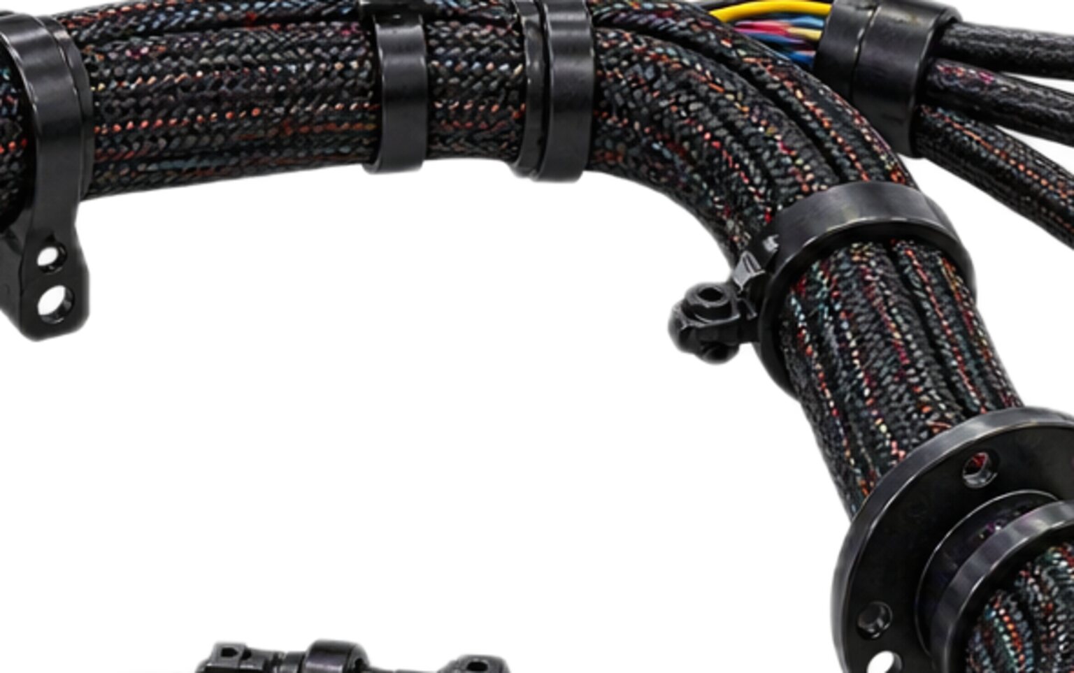
A harness is drawn as a schematic and lives as an object. The schematic says what connects to what. The object has to get there across a machine that vibrates, flexes at its joints, heats up on one side, gets washed down on the other, and gets climbed on by people who are thinking about something else. Routing is the part of harness design where the electrical drawing meets the steel. It is the mechanical design of an electrical part, and it decides more of the harness's service life than the choice of any conductor in it.
The schematic cannot fail in the field. The route can. A harness fault that arrives months after commissioning is often a routing fault presenting as an electrical one: a conductor broken inside intact insulation at a clamp edge, a jacket worn through on an edge nobody drew, a connector full of water because it sat at the low point, a pin backed out because the wire was holding the weight of the loom. None of those was a wrong wire. Each was a right wire in a wrong place.
The route is a tree laid on the machine
A harness has a topology before it has a route. The topology is the tree: a trunk, the points where it branches, the breakouts that leave the trunk and the connectors they end in. What decides where the tree branches is where the destinations cluster on the machine and which circuits may travel together. That last constraint is fixed before anything else. Safety circuits never share a bundle, a splice or a shell with power, so the tree is at least two trees from the start, and often more, running the same general path without ever becoming one bundle.
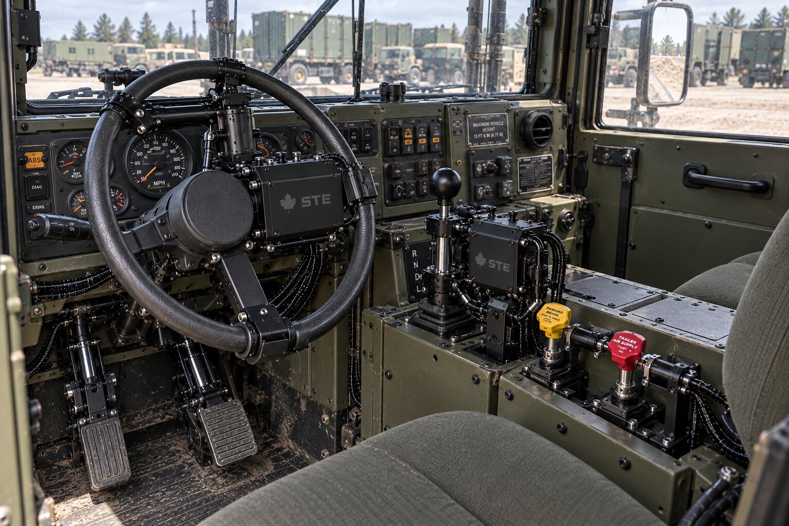
The route is that tree laid onto a real structure. Every branch point has to sit somewhere it can be clamped. Every trunk section has to find a path along a member that does not move relative to the clamps on it. Every crossing from one member to another that moves relative to it is a joint, and a joint is a separate engineering problem from a run. Every pass through a bulkhead is a hole, and a hole is an edge. Every breakout has to arrive at its connector with the connector supported, the bend before it within the cable's limit, and a length of slack that somebody will need later.
The drawing shows all of this cleanly. The machine does not. Between the drawing and the machine sit the hoses that were re-routed after the model was frozen, the bracket that was moved to clear a guard, the weld that is not in the model because welds never are, and the door that swings further open than the model shows because the stop was changed. The route has to survive the machine as it is, not the machine as it was modelled, and that is why nobody cuts from a model.
Bend radius is a property of the cable
Every cable has a smallest bend it can take without damaging itself, and it is not a guideline. It is a property of the cable's construction, stated by the cable's maker, and the route either respects it or damages the cable. It is normally stated as a multiple of the cable's own diameter, which means a thicker cable needs a wider bend, and the conductor that was chosen to carry more current is the one that bends worst. The harness designer is trading one against the other on every branch.
What happens inside a bend that is too tight is not subtle. The strands on the outside of the bend stretch and the strands on the inside compress, and where the bend is tight enough the outer strands yield. A foil shield cracks along the bend line and the shield now has a slot in it. A braided shield opens up, its coverage drops, and it stops being a shield at the one place it is most likely to be near a source of interference. In a twisted pair the twist geometry is disturbed, and a data bus that was matched along its length is no longer matched at the bend. The jacket may look fine. The jacket usually looks fine.
The route respects the radius or it does not. There is no partial compliance. Where a breakout has to turn a corner, the corner is planned with the radius in it, which means the connector is placed far enough from the trunk to allow the turn, or the trunk is moved. Where a cable enters a connector, the backshell has to let the cable leave straight and turn after it has left, or a right angle backshell is specified so the turn happens inside a fitting designed for it. A route that meets its radius everywhere except at one connector has met it nowhere that matters, because that connector is where the fault will be.
Nothing is fabricated until the drawing is signed.
A bend made once and a bend that moves
A bend at a fixed point is set once at assembly and then never moves. The cable takes its shape, the strands settle, and the bend carries the same small stress for the life of the machine. That is one engineering problem, and it is solved by respecting the radius.
A bend at a joint moves every time the joint does. An articulating boom, a slewing upper structure, a door, a tilting cab, a steering knuckle, a payload bay that opens: every one of them puts a harness across a line where one side moves and the other does not. That bend flexes for the life of the machine, and it is a different engineering problem, because the failure is not overstress. It is fatigue.
Bend a paperclip once and it holds its new shape indefinitely. Bend it back and forth at the same spot and it breaks in your hand, at a load that was never enough to break it once. Copper strands do the same. A conductor that flexes at one point work-hardens at that point, the strands break one at a time, and the conductor's cross section shrinks with every broken strand until the last few carry all the current, heat, and part. The insulation is intact the whole time. From the outside, the cable is fine. From the inside, it has been failing since the first month.
A cable meant to flex is built differently. It carries many fine strands rather than few coarse ones, so that each strand sees less strain in the same bend. It carries a jacket compounded to flex without cracking, and a shield constructed so it can move with the cable. Its maker states a second radius, larger than the fixed one, for the bend that moves. Specifying a fixed-installation cable across a moving joint is specifying the failure.
The route at a joint is designed around the motion. The clamps on either side define a flexing length long enough that no part of it bends tighter than the flex radius, and short enough that it does not swing, because a swinging loop finds an edge. A pivot is crossed by bending, not twisting; an unavoidable twist is spread along a free length, never taken at a point. Where the cable runs in flexible conduit, the conduit is rated to flex and clamped so that the cable moves inside it.
None of this is settled from a drawing of the joint at one position. It is settled with the joint moved through its whole travel, with the cable in place, watching where it goes.
Chafe, and the edges nobody drew
Chafe is the slow wear of a jacket against something that is not moving with it. It does not need gross motion. Vibration alone is enough, and a machine with an engine, a hydraulic pump or a set of actuators has vibration everywhere. A harness resting against an edge under vibration is being sawn, slowly, and the saw never stops while the machine is running.
The wear has an order. The jacket polishes first, then thins, then opens. Under it the shield wears, then the insulation of the outer conductors, then the conductors. The first electrical symptom is a short to chassis that appears only on a bump and clears when the machine settles. It is the worst kind of fault to find, because the machine has to be moving to show it, and then it is gone. Later it becomes a hard short, or an open, and by then the jacket has been open for months and water has been travelling inside it.
- Every crossing and every edge gets protection, and the ones that matter most are the ones nobody drew.
- The model shows a bracket as a clean rectangle.
- The real bracket has a sheared edge and a burr.
- The model shows a hole.
- The real hole was punched and never deburred.
- The model does not show the weld spatter beside the seam, the end of a bolt where the thread runs out past its nut, the tail of a hose clamp, or the cut end of a cable tie, which is a small blade if the tie was cut with side cutters instead of the tool that cuts it flush.
- A hydraulic hose routed alongside the harness after the harness was drawn moves under pressure and its cover is an abrasive, and it will cut a jacket long before the harness marks the hose.
- The first choice for chafe protection is air.
- A harness that touches nothing cannot chafe on anything, so the route is planned to stand the bundle off the structure wherever that is possible, on clamps that hold it clear.
- Where it must cross an edge, the edge is trimmed or the harness is sleeved, and the protection is fixed so it cannot migrate off the edge and leave the jacket where it was.
- Where it must pass through a hole, there is a grommet in the hole, sized to the bundle, and the bundle is clamped on both sides so the grommet is not the thing holding it.
- Where it must run alongside a hose or another harness, they are clamped together so they move together, or they are kept apart so they cannot touch.
- The protection is on the drawing, at a marked position, and it is specified.
- Protection added on the line because somebody noticed an edge is better than none, but it is a route that was not finished.
Water finds the low connector
Water on a machine does not stay where it lands. It runs along whatever it lands on, and a harness jacket is a path. It travels along the jacket to the lowest point and hangs there. If the lowest point on a run is a connector, the water is now sitting on the seal, and it will sit there until it dries, freezes or gets in. A seal that sheds a spray is not a seal that holds a standing drop for a season. A connector at a low point fills eventually.
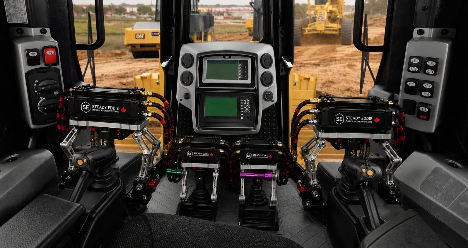
Inside, the water does its usual work. The contacts corrode, the resistance across the mated pair rises, and a circuit that was fine becomes intermittent. The fault presents as an electrical one, somewhere downstream of the connector, and the technician chasing it may be some distance from the low point that caused it.
The drip loop is the answer, and it is a routing decision, not a connector decision. The harness drops below the connector and then rises into it, so that the lowest point on the run is a length of jacket and not a seal. Water runs to the bottom of the loop and drips off. The connector enters from below or from the side, never from above, so that nothing can pool on its face. Where a connector has to face upward, it is covered and the drainage is somewhere else. Where a machine is pressure washed, the connector is placed on the side of the structure away from the spray, because a pressure washer drives water past seals that were designed for rain.
The wire holds nothing
A termination is an electrical joint. It is not an anchor. The crimp that joins a conductor to a contact is a cold weld made by a die, and it is designed to carry current. It is not designed to carry the weight of a harness, the pull of a person, or the load of its own cable hanging from it. The wire never holds the weight of anything, including itself.
The mechanical load path is designed separately. The backshell's strain relief grips the jacket or the bundle and carries whatever pull reaches the connector. The first clamp behind the connector carries the weight of the harness, and it is placed close enough that the length between it and the connector cannot swing under vibration. That length is slack. It is not stretched straight, because a straight length under vibration puts the contacts in tension with every cycle. On a vertical run the top clamp carries the weight and every clamp below it is a guide, so that the connector at the bottom carries nothing.
The contact retention system in a connector housing is designed to keep a contact in its cavity against the force of mating and unmating. It is not designed against a sustained pull, still less a cyclic one. A contact under a steady pull, vibrated, works its retention clip a little further open each cycle, and one day it backs out of the cavity far enough to lose contact with its mate. The connector is still mated. The pin is still in the housing. The circuit is open. If that circuit is a feedback line, the actuator it belongs to has lost its position signal. If it is a link in an emergency stop chain, the machine stops and nobody can find out why, and the next bump closes the pin again, so the chain reads healthy and nothing says what stopped it.
Slack somebody will need
A harness will be worked on. A connector will be unplugged to fault-find behind it, and the person unplugging it will need to pull it clear of its bracket to see the pins. A contact will be damaged and need to be replaced, which means cutting back the conductor and terminating again, which means the conductor is now shorter. A panel will need to open fully with the harness still connected. A component will be replaced with one whose connector is not quite where the old one was. Every one of those needs slack, and the slack either exists where it is needed or the job is done badly.
A service loop is that slack, designed in. It is a defined length, at a defined place, secured so that it is neither a chafe point nor a handhold. It is drawn, because slack that is not drawn does not arrive, and slack that arrives where it was not drawn becomes a loop that swings against an edge. The loop sits behind the last clamp before a connector, or behind a panel, formed and tied so it holds its shape and can be released when somebody needs it.
A harness cut to exact length is terminated once, correctly. The first time a connector is re-terminated in the field, that branch is too short. The technician has a machine that must run, a conductor that will not reach, and a truck with a splice kit in it. The splice they make is the worst joint on the machine. It was not on the drawing, it was made with whatever was to hand, in the field, in the weather, and it sits in the bundle with no record that it exists. Nothing is fabricated until the drawing is signed, and a field splice was never drawn. A service loop is the length that stops it being made.
A person will stand on it
The route has to survive people, and three people in particular. The first stands on it. A loom that crosses a step, a deck plate or the floor of a cab is going to have a boot on it, in mud, with the person's weight coming down. The route keeps looms out of the places boots land, and where a loom must cross one it runs under a guard or inside a channel that takes the boot, not the harness.
The second uses it as a handhold. A bundle at the height a hand reaches while climbing onto a machine will be grabbed, and the grab will be a full body weight, suddenly, with a gloved hand. The route keeps bundles out of the reach of anyone climbing, and where it cannot, the bundle is clamped so that a hand pulling on it pulls on the clamps and the structure, never on a connector. A bundle that can be pulled taut against a connector by a person's weight has a connector that will fail.
The third is doing maintenance in the dark. They have a light in one hand and a tool in the other, they are lying on their back under the machine, and they are going to unplug a connector by feel and pull it by the wire because the wire is what they can reach. The route puts connectors where a hand can find them and grip them by the body, with the release accessible, with slack behind them so the connector can be brought to the light. It puts connectors of the same family far enough apart that a hand in the dark cannot swap them, and it leaves the last refusal to the keying of the connector itself.
Separation is kept through the route
Separation is decided in the bundle, not in the route. The safety rule and the clearance between a data bus and a motor feed are drawing decisions, made before the route, and they produce separate bundles running the same general path.
The route can undo it. Two bundles that leave the drawing separate meet a bulkhead with one hole in it, and the person on the line puts both through the hole, because it is the hole that exists. Now the safety chain and the power feed share a grommet, and inside the grommet they are separated by one wall of insulation each. Two bundles run alongside each other on a long member with one row of clamps, and the clamps hold them together, and the data bus spends its whole length lying against the motor feed it was separated from at the drawing stage. Separation that is maintained in the bundle and lost in the route was never maintained.
So the route carries the separation all the way. Separate bundles have separate clamps or a divided clamp. They have separate pass-throughs, and where a bulkhead has to carry both they pass through separate grommets in separate holes, or through a divided fitting that keeps them apart inside it. Where a signal bundle has to cross a power bundle it crosses, at one point, and does not run alongside. Where a bundle passes something hot, such as an exhaust or a hydraulic component under load, it stands off from it, because the insulation rating of a cable is stated for the cable's own temperature, not the room's. Where the assembly is a fixed installation, CSA and the Canadian Electrical Code carry requirements for how circuits are separated and how conductors are protected, and the route is where those requirements are met or lost. On a machine the same principles hold regardless.
Nobody cuts from a model
A route cannot be finalised from a model. Where the set states no length, somebody walks the route on the machine, and until then that length does not exist.
The model is a statement of intent about a machine. The machine is the fact. Between them is every gap already named, plus two: the actual stiffness of the actual cable, and a mating connector that arrived from its supplier a little different from its drawing. Every one of those changes a length. A cut list written from a model that nobody walked is a list of guesses, and the harness that comes off it is scrap.
Scrap in both directions. A branch that comes up short cannot be fixed. It can be spliced, which puts an undrawn joint in the bundle, or it can be pulled to reach, which loads the termination that was never meant to carry load, or the whole assembly goes back. A branch that comes up long is not safe by being long. The extra has to go somewhere, and where it goes is a loop that was not designed, at a place that was not chosen, and it will find an edge or a boot or a hand. Every length is right or it is wrong. There is no side to err on.
The walk is a physical act. A person takes the drawing, a set of connectors or dummy connectors for the ends, and a length of rope or scrap cable of the same construction as the real thing, and lays the route on the machine. They put the machine in every position it can take: boom up and boom down, door open and closed, cab tilted, seat forward. They mark every clamp position on the structure. They mark every pass-through and check that it has an edge treatment. They form every joint loop through its whole travel and adjust it until it is clear at every extreme. They place every drip loop and every service loop. And then, with everything marked and every position tried, they measure between the marks. That measurement is the cut length. A value nobody measured never reaches a wire.
The walk produces the manufacturing detail the formboard is drawn from. Clamp positions, protection positions, cut lengths, breakout positions and the orientation of every connector all come off the machine and go onto the drawing. We build to a customer's issued set and we return the manufacturing detail, and the walk is where most of that detail is made. The first assembly is built to the walked drawing once it is signed and offered up to the machine, and anything the walk missed is corrected on the drawing before the run is released, not on the line. The walk is the cheapest part of the job.
What we refuse
We do not issue a cut length that nobody measured on the machine or issued on the drawing. A model gives us a route to walk. It does not give us a length to cut.
We do not route a safety circuit through a passage shared with power because the passage was there. If a bulkhead has one hole, it needs a second one, and that is a conversation we have before the harness is built, not one the fitter has with a grommet.
We do not let a connector carry weight. If the structure does not offer a clamp point close enough to the connector to take the load, the structure needs one, and we say so.
We do not specify a fixed-installation cable across a moving joint, and we do not clamp a joint loop at the point where it flexes.
We do not accept "route it as best you can" as an instruction. A route that is left to the fitter's judgement on the day is a route with no drawing, and nothing is fabricated until the drawing is signed. We would rather walk the machine once more than build a harness to a guess.