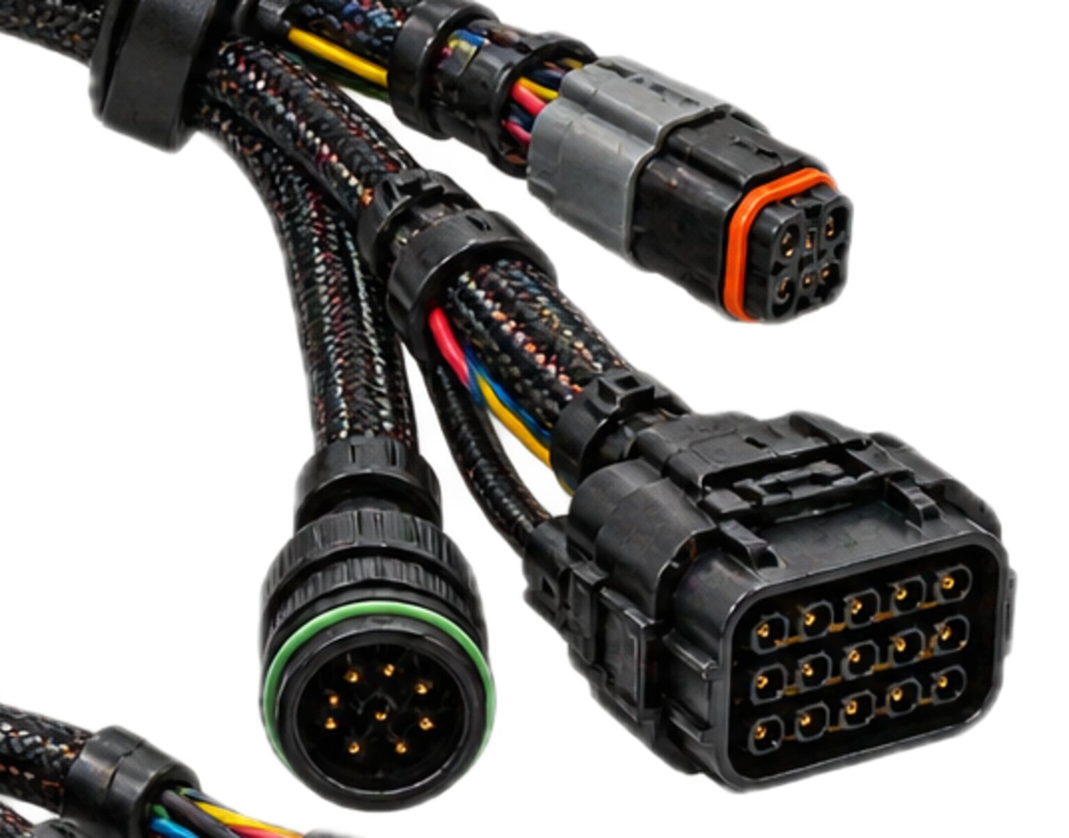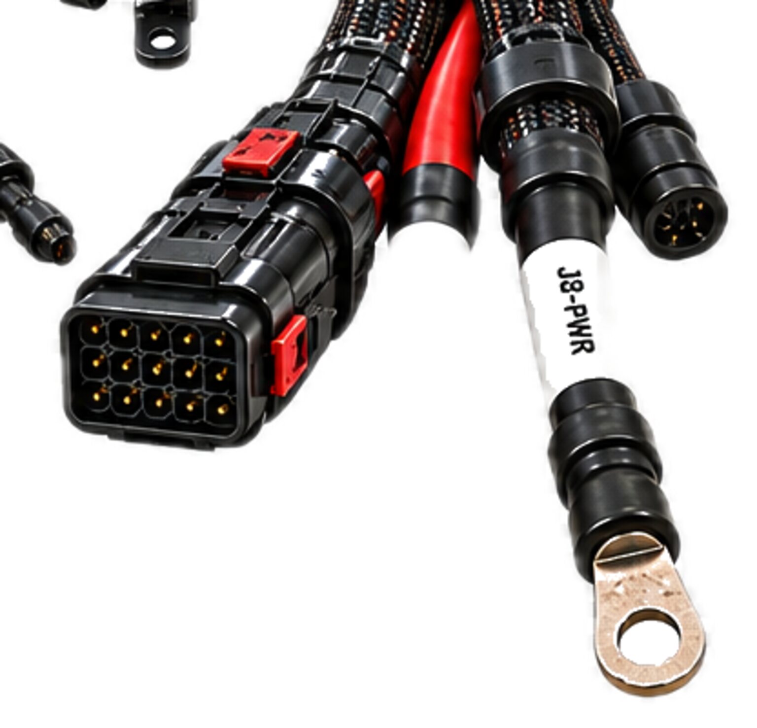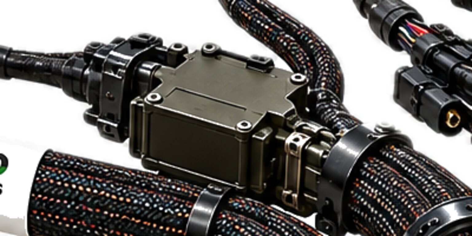
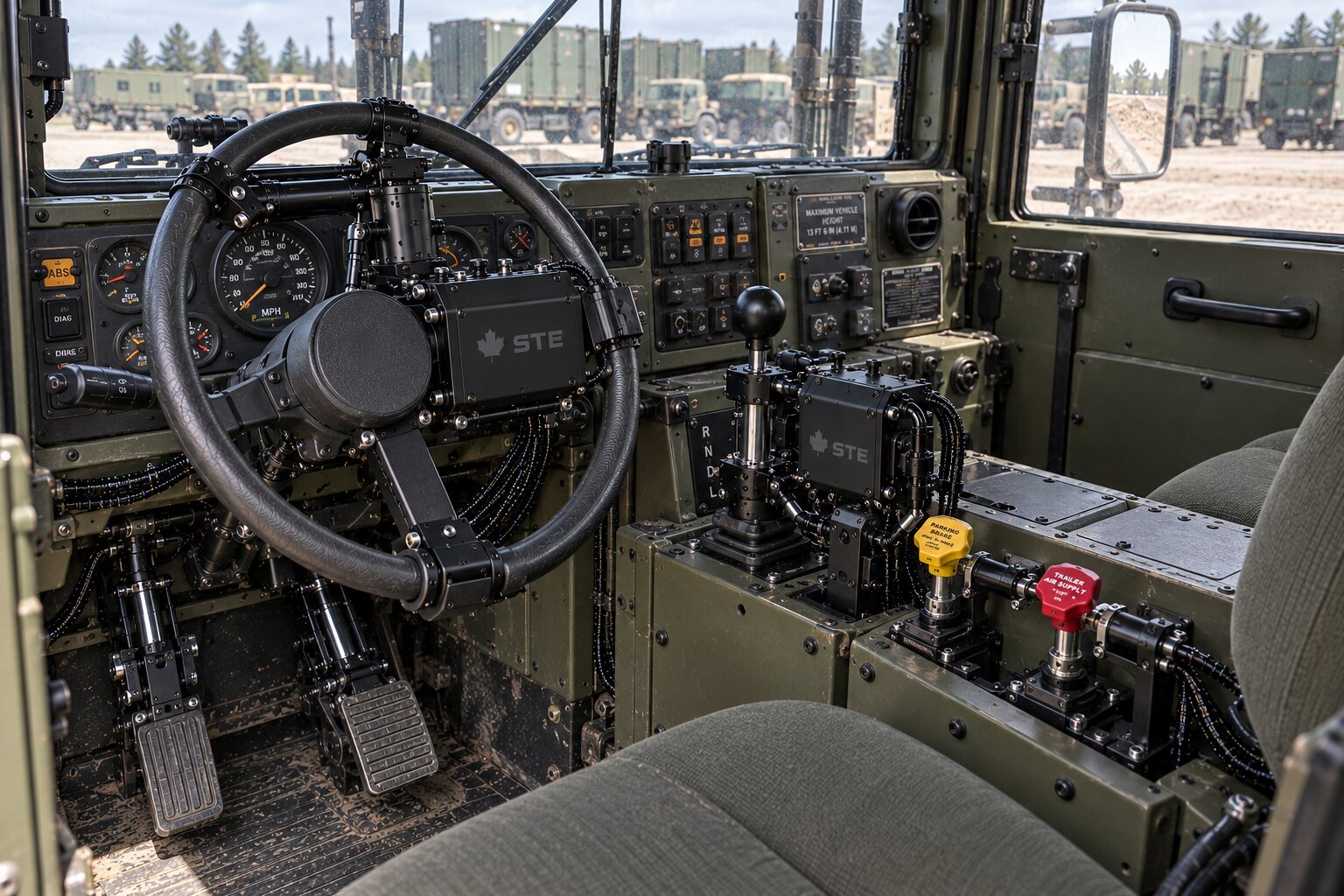
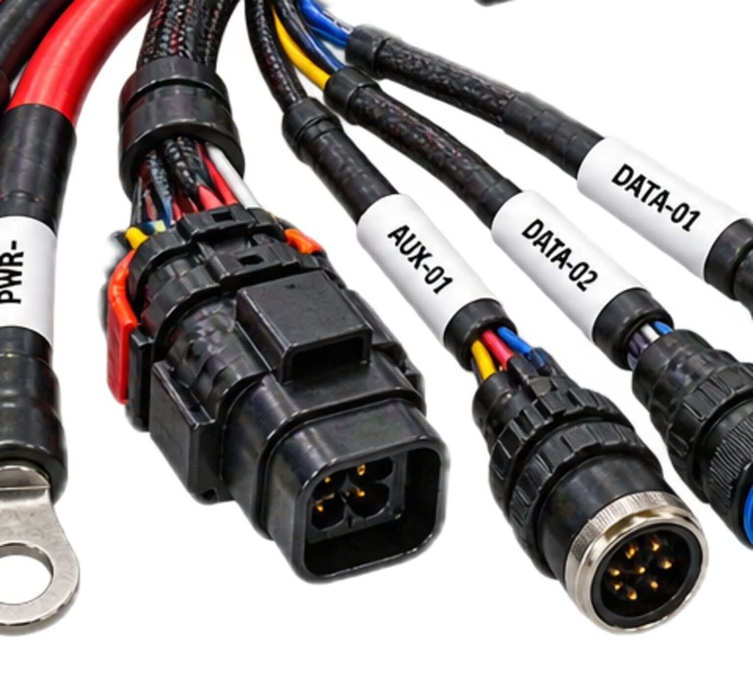
Everything else in a harness is fixed at build. The connector is the exception. It is the one part of the harness designed to be opened, and it is opened by a person, in the field, usually not the person who designed it, and usually not under the conditions the designer was picturing.
That makes it the hardest joint in the harness. Every conductor carries its circuit identity, end to end, and at the connector that identity is handed across a face a hand can separate. Power, data, ground and the safety chain arrive at the same edge of the machine at once, a contact pitch apart, in a shell that a person will mate and break for years. On a machine that runs without a person there is nobody in the cab to notice when it goes wrong.
Where the harness ends
Two things meet at a connector, and neither of them is copper. The first is the harness, which is fixed. The second is an act, which repeats: a person offers a plug to a receptacle and turns the coupling until it locks. The harness has to be right once. The act has to be right every time, in every condition, by every person who will ever do it.
The connector is also where two owners meet, and that meeting is the seam. One side of the face belongs to the harness and the other to the equipment it lands on. Each side promises the other a set of things. The contact map, which says which circuit sits in which cavity. The keying, which says which plug reaches which receptacle and in which orientation. The mate order, which says what touches first and what parts first. The sealing class, which says what weather the joint keeps out. And the condition of the face when nothing is mated to it, which says what is live and exposed when the plug is out. When one side changes any of these, the other side has changed too, whether anyone told it or not. That is why the interface is a drawing and not a conversation.
Where the equipment side belongs to a customer's machine programme, that programme owns the interface. We build to a customer's issued set and we return the manufacturing detail: the contact map as built, the keying as fitted, the seal sizes and the test record, so that the next harness built to that interface is built to the same thing. Nothing is fabricated until the drawing is signed.
Where a finished assembly sits for approval is set out under CSA and the Code.
What sits where in the insert
A connector insert is a small piece of topology. Every cavity is a place where a circuit surfaces, and the arrangement decides which circuits are neighbours. Neighbours matter, because the failures a connector suffers are failures between neighbours: a bent pin, water bridging two cavities, a strand escaping a crimp. The layout of the insert is a decision about which circuits are allowed to fail into each other.
The shop zones contacts by service. A service is a family of circuits that share a voltage, a reference and a fault behaviour: motor or bus power and its returns; low-level signal and its returns; data pairs and their drains; chassis ground and bond; and the presence loop that tells the machine the plug is home. The emergency-stop chain is not in a shell with power at all. Each service occupies its own block of cavities. Blocks are separated by a boundary that is not a live contact: a spare cavity fitted with a sealing plug, a ground contact, or the wall of the insert itself. Returns sit beside the power they belong to. A data pair sits together with its drain and stays twisted to the back of the contact, so that the designer's pairing survives right up to the face.
The rule that governs the layout is that no presence or safety contact ever sits adjacent to a power contact, including diagonally. A fault that bridges the two can do one of two things, and both are worse than an open circuit. It can hold a presence loop closed on a plug a person has just started to pull. Or it can put power onto a safety input built to see a contact closure, and destroy it. The shop meets the adjacency rule in the strongest way there is: safety circuits never share a bundle, a splice or a shell with power. The zone boundary for the safety service is the shell wall, and the two shells are keyed so that neither plug can reach the other's receptacle. Where an issued interface cannot be met that way in the shells it specifies, that is raised on the drawing before anything is cut. The same separation runs the whole loom, and the rule for it is set out under segregation.
Zoning is settled on the drawing, and nobody chooses a cavity at the bench because it is empty. A contact goes where the contact map puts it, or the map is wrong and the map gets fixed first.
A value nobody measured never reaches a wire.
One way in
A plug goes into its receptacle one way, or it does not go in. That is the whole of the keying rule, and the shell does the work, not the pins.
A keyed shell carries a master key and keyway, and the keyway engages before any contact can reach any other contact. Offered in the wrong orientation, the plug stops at the shell face with its contacts still inside their own housing, untouched. Only when the key finds the keyway does the plug travel, and then it travels to the only contact arrangement the drawing allows. Pins are never the thing that says no. Pins that say no are pins that get bent.
Where a machine carries a family of connectors of the same shell size close together, keying does a second job. Each receptacle in the family is fitted with a different key position, so that a plug for one refuses every other, and where a family outgrows the key positions the shell offers, the drawing changes the shell size or the insert rather than repeating a key. This is what stops a motor feed being landed on a sensor port at a service exchange in the rain. A colour band helps the eye find the right port in daylight. The key is what tells the hand in the dark, and the hand is the one doing the mating.
Keying is therefore a design decision, not a shop convenience. Key positions across a machine are allocated on the drawing set, once, and every harness for that machine is built to the same allocation. A connector that enters its receptacle two ways is not a connector with a minor defect. It is a connector with two contact maps, one of them wrong.
The order of making and breaking
The safe way to mate a connector is a sequence. Ground makes first, so that both sides share a reference before anything else touches. Power and signal make next, onto a joint that is already grounded. The presence loop makes last, when everything else is seated. Breaking runs the sequence in reverse: the presence loop opens first, then power and signal, and ground breaks last of all.
The person is not asked to know this sequence. The geometry allows no other. Contact length does the ordering: the longest contacts meet first and part last, the shortest meet last and part first. The ground and bond contacts are the longest in the insert. The presence contacts are the shortest. The shell engages before any contact does, so that on a metal-shelled connector the shells are bonded while the contacts are still apart. The coupling, whether bayonet or thread, cannot reach its lock until every contact is fully seated, so a locked connector is a fully mated one by construction.
| Service | Contacts | Makes | Breaks |
|---|---|---|---|
| Shell and bond | the shells themselves, before any contact | first | last |
| Ground | the longest contacts in the insert | after the shells | after everything else |
| Power, return, signal and data | standard-length contacts | after ground | before ground |
| Presence loop | the shortest contacts in the insert | last | first |
The presence contacts being shortest is the part that carries the most weight. A pair of them is wired as a loop the machine reads as presence: closed means the plug is fully home, open means it is not. Because those contacts make last, the machine cannot see the plug as present until power, signal and ground have already made. Because they break first, the machine sees the plug leaving before the power contacts have parted, and the controller has that interval to drop the load. The interval is only as long as the hand is slow, so the power contacts are chosen to survive parting under load as well. A power contact that parts under load arcs, and every arc pits the plating.
Look at the plug on any corded tool in the shop. The ground pin is longer than the other two. It enters first and leaves last, and nobody has ever had to think about it. The connector on an autonomous machine does the same thing with more services and less forgiveness.
Mating it in the dark
The condition to design for is not the bench. It is a person in the dark, with gloves on, on a machine whose engine is running, who cannot see the index mark and could not read it if they could.
- The person finds orientation by feel, so the keyway is coarse and the lead-in is distinct enough to be felt through a glove.
- The person has to know when the connector is locked without seeing it, so the coupling gives a detent that can be felt and heard: a bayonet dropping into its stop, a thread coming hard up against a shoulder.
- The person will let go the moment it feels done, so the connector must not have a state that feels done and is not.
- A plug that seats halfway and rests there is the worst thing a connector can do, because vibration will walk it the rest of the way out, and the fault it produces will clear itself every time somebody pushes on it.
The coupling has to stay locked on a machine that vibrates all day. A thread backs off under vibration unless something stops it, so the coupling carries an anti-decoupling ratchet or a lock that has to be deliberately released. A bayonet is held by its detent and its spring. The person will use the connector as a handle, so the shell and the coupling carry that load and the contacts never see it. The connector will be stepped on, dropped in mud, hosed down, left in the sun and then frozen, and every one of those works the seals. A seal compressed and released across a season of temperature swing takes a set, and a seal with a set has stopped sealing.
What vibration does to the contacts themselves is quieter. Two mated contacts allowed even the smallest relative motion rub, and the rubbing wears through the plating and grinds the wear into oxide. The joint that results is not open and not closed. It is a resistance that changes with temperature and with whether anyone has touched it recently. The defence is stillness. A locked coupling, a backshell that clamps the cable and a receptacle that is properly mounted make the contact interface the one point in the joint that does not move.
Backshells, strain relief and sealing
The wire never carries the load. Every force that reaches a connector, a pull, a swing, a bend at the exit, the shock of a drop, is carried by the shell and the backshell and delivered to the panel through the receptacle mount. The load path runs from the cable jacket into the backshell clamp, from the clamp into the shell, from the shell through the coupling into the receptacle, and from the receptacle into whatever it is bolted to. The contact and its crimp are in the electrical path and in no other. A crimp asked to hold a cable is a crimp that will fail, and it will fail at the wire, one strand at a time, where nobody can see it.
The backshell is chosen for the exit. A straight backshell where the cable can leave along the mate axis; an angled one where it cannot, so that the cable turns inside a fitting built to turn it rather than in free air. The bend is taken in the boot region of the backshell, over a radius the fitting sets, and never at the rear of the crimp. A cable that bends at the rear of the insert bends the conductors where they are held rigid, and that is where they break. Where the harness is shielded, the shield terminates at the backshell, all the way round, and the rule for that termination is set out under shielding and bonding.
Sealing is a set of seals, and the connector is only as sealed as the worst of them. There is the interfacial seal, compressed between plug and receptacle when the coupling locks. There is the rear grommet, through which every conductor passes, each through a wire seal matched to the insulation it grips. That is why insulation diameter is a build fact chosen with the connector and never after it: a conductor with the wrong insulation for its seal is a conductor with a leak around it. There are the sealing plugs, one for every cavity that has no contact, because an empty cavity in a sealed connector is a hole, and a missing cavity plug is the most common way a sealed connector turns out not to be. And there is the boot, adhesive-lined, shrunk over the backshell and onto the jacket.
Behind all of this is the contact itself. A crimp is a cold joint: strands and barrel pressed into one solid piece with no air in it. A sample of every crimp set-up is pulled and sectioned before the run, and the section shows whether the barrel has closed on the strands or merely around them. Each contact, once inserted, is pushed home until its retention clip clicks, then pulled back to prove that it is held.
The unmated state
A connector spends a large part of its life open. A payload port on a carrier is open whenever the payload is off. A service port is open until the day it is needed. The design question for the open state is what is live on the face and what the weather can reach, and it is decided before the connector is chosen.
The live side gets the sockets. A socket contact is recessed in its insert, and an unmated receptacle full of sockets presents a face that a finger, a dropped tool or a loose strand cannot short across. The dead side gets the pins, so that the pins are on the part that carries no power when it is in someone's hand. On a carrier and payload seam that means the carrier, which has the battery, carries sockets, and the payload plug carries pins.
Then the port is de-energised anyway. The same presence loop that makes last and breaks first tells the machine that nothing is mated, and a port with nothing mated to it is a port the machine does not feed. Power on an open face is a design fault even when the contacts are recessed, because water does not need a finger.
The cap is part of the connector. It seals to the same standard as the mate, with its own seal and its own coupling, and it keys and locks the way a plug does. It is tethered to the shell, because a cap that is not tethered is a cap in the mud. What an uncapped receptacle suffers is condensation: warm air enters on a warm day, cools overnight, and leaves its water on the contacts. The contacts turn green a season later, the resistance of the joint goes up, and the first anyone knows of it is the day the payload does not answer.
What a keying proof proves
On a finished assembly, before it leaves, every plug is proved against its keying. The plug is offered to its own receptacle in every wrong orientation, and it must refuse each one at the shell, without a contact touching. It is offered to every other receptacle on the assembly it could physically reach, and it must refuse them all. Then it is offered to its own receptacle the right way, and it must seat and lock.
- What that proves is specific.
- It proves that the key position on the drawing is the key position on the part.
- It proves that the alternate keying across a family of ports is distinct port by port.
- It proves that the key and keyway are undamaged, because a damaged key admits a plug it should refuse.
- And it proves the contact map, indirectly, because a plug that could enter a second way would place every contact in a second cavity, and the keying proof rules the second way out.
- It does not prove continuity.
- That is the job of the continuity check, which proves that every contact carries the circuit identity the map assigns to it and no other.
- It does not prove segregation.
- That is the job of the isolation test, which asks whether two circuits that must never meet are in fact separate.
- It does not prove the seal, and it does not prove the mate order, which is inspected in the insert before the connector is loaded.
- Keying proves that the identity the harness carries can only be delivered to the port that expects it.
- A finished assembly leaves with all of these on its record, described under test and acceptance.
How a connector fails, and when
The fast failures show at first power-up. A pin bent by a forced mis-mate presents as one dead circuit, or as a short between that circuit and its neighbour. A plug seated in the wrong receptacle of a family presents as everything wrong at once, which is the good version, or as one thing quietly wrong, which is the bad one. A contact pushed in and never pulled back presents as an open circuit on a connector that looks perfectly mated, because its own mate has pushed it out of the rear of the insert.
The slow failures arrive over a season. A partial mate that felt done walks out under vibration and presents as an intermittent, weeks after the last person touched it. Fretting presents on a cold morning as a sensor that reads wrong and then reads right, and as errors on a bus that passes every test at the bench, because the resistance it adds is small until the temperature drops and large until someone moves the plug. Water through a missing cavity plug or a boot that was never shrunk presents as corrosion, then as leakage between neighbours. A wire made to carry the load because the backshell was never clamped presents as an open circuit on the day a technician pulls the cable to look at something else. Power contacts that have parted under load present as heat: pitted plating, rising resistance, an insert discoloured from the back, found by touch and smell before it is found by a meter.
The worst timing is the intermittent that clears when it is touched. A technician arrives, handles the connector, the fault clears, the technician leaves, and the fault returns. On a machine with no operator it is a halted machine on a site nobody is standing on, or a payload that stops answering with the aircraft still in the air.
Who pays
An intermittent connector in a safety chain presents as a nuisance stop: the machine halts, nothing is visibly wrong, and it restarts when the plug is pushed. The hazard is not the stop. The hazard is what a crew does after the tenth stop, which is to start treating the safety chain as the problem. A connector that stops a machine falsely is teaching the people around it to distrust the one circuit that is meant to stop it. That is paid for in the currency of the next stop that was real.
The other currencies are the ordinary ones. A truck roll to a remote site to find a fault that is not there while anyone is looking at it. A machine down for a day because a contact map changed on one side of the interface and nobody told the other. Every one of these costs more than the connector did.
What we refuse
We refuse to place a safety contact next to a power contact, and we refuse to put the safety chain in a shell with power at all. Where an issued interface asks for it, we raise it on the drawing before anything is cut.
We refuse a shell that can be mated in more than one orientation, and we refuse to allocate a key position at the bench. Keying is on the drawing set, once, for the whole machine, or it is not keyed.
We refuse a connector whose cable carries the load. No backshell, no strain relief, no build. We refuse an empty cavity without a sealing plug in a sealed connector, a wire seal not chosen for the insulation passing through it, and a boot that is on the drawing and not on the part.
We refuse a live pin side on an open face, and we refuse a port without a cap that seals, keys and locks. We refuse a mate order that depends on the person reading the manual.
We refuse to substitute a shell, an insert, a contact or a backshell on the floor because the specified one is on order. A substitution is a revision, the revision is signed before it is built, and the manufacturing detail goes back to whoever owns the interface. A connector is the part of the harness another party builds to, and a part nobody specified never reaches a harness we build.