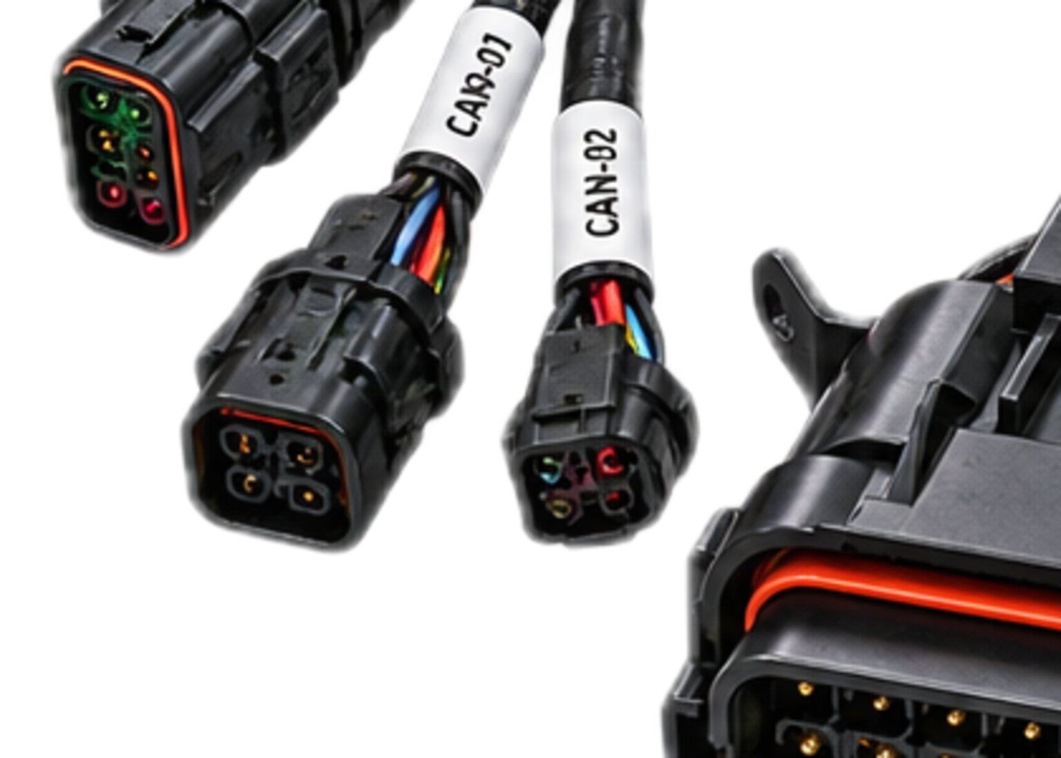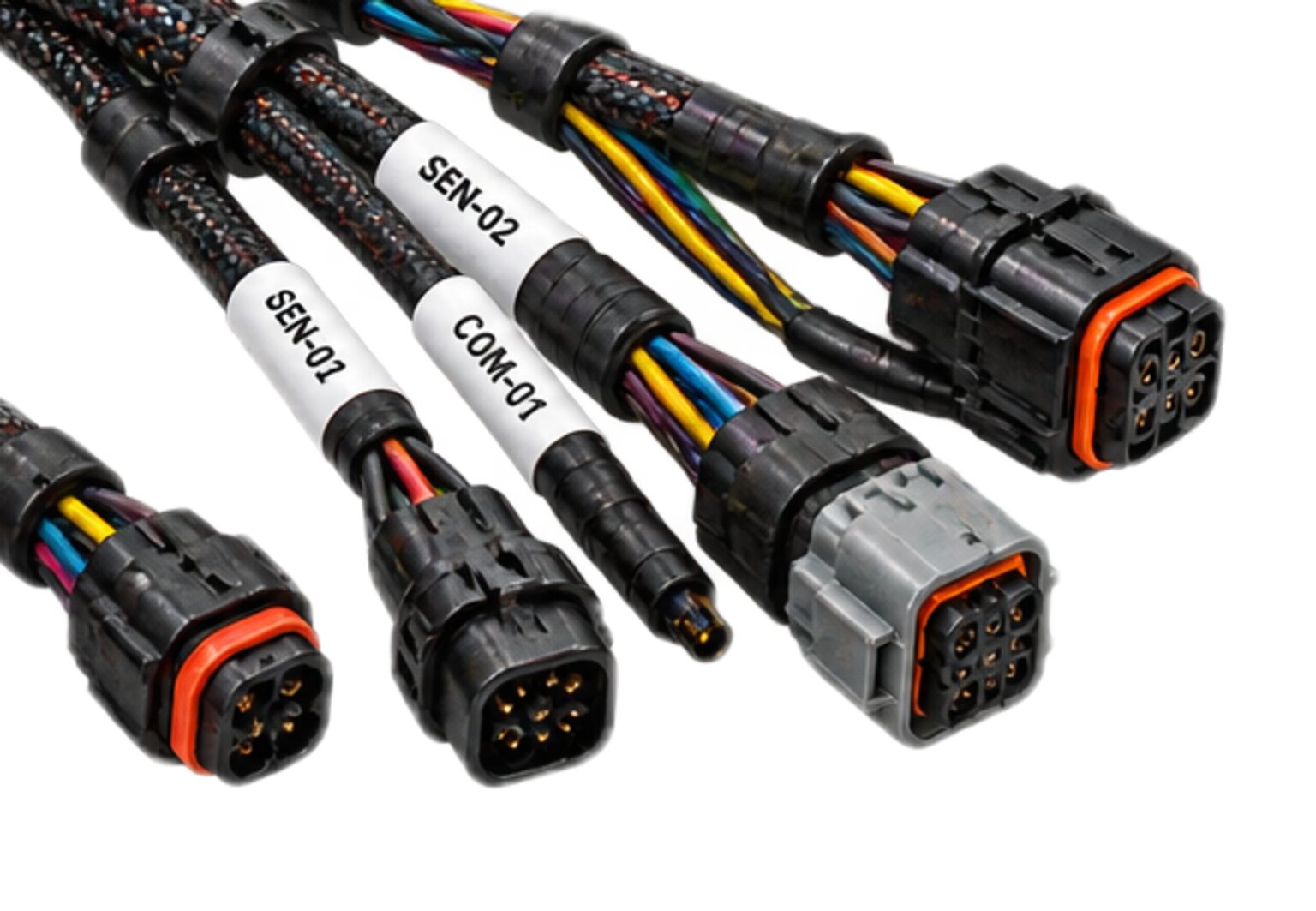
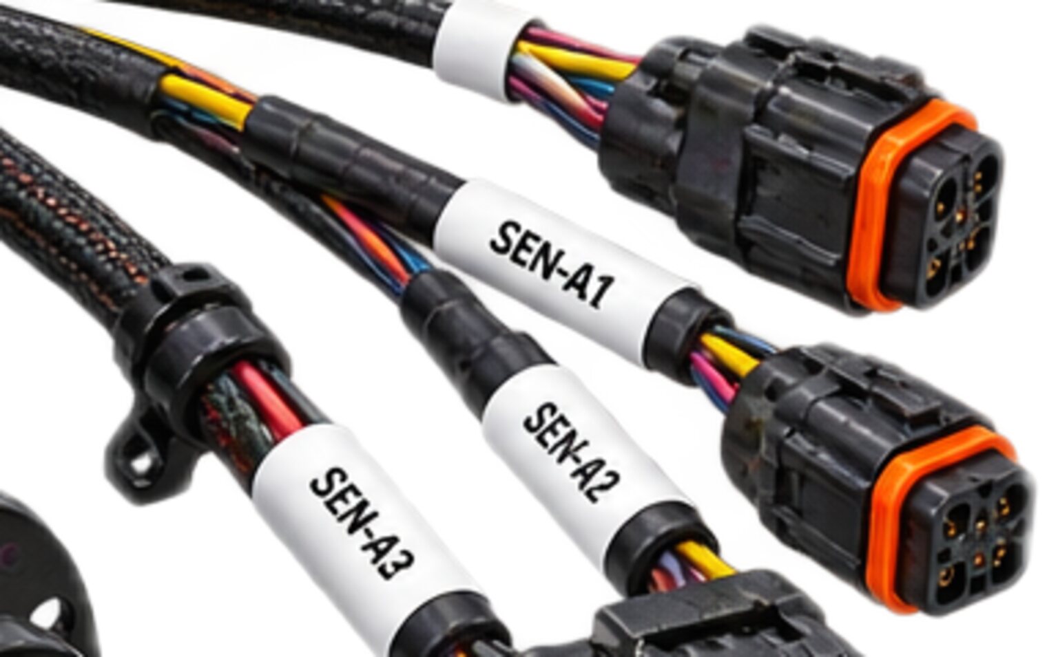
A carrier arms on the word of a circuit it did not build. The payload arrives with its own interlock conductors, its own contacts and its own state to report, and the carrier's arming logic reads that chain and decides whether the machine may go live. Everything else at the seam can be wrong and the machine stays inert. The interlock is the one part of the matched set that, built wrong, lets the machine go when it should not, or holds it when it should not, and the second of those failures is what teaches people to defeat the chain and so produce the first. It is the part the other three harnesses are not allowed to touch.
The mechanism
The interlock harness is a small bundle of conductors with one job: to carry the chain the carrier's arming logic reads. It runs from the carrier's safety controller, out through the seam connector to the payload, where the payload's own contacts close and open the links as its state changes, and back to the carrier. The current it carries is the sense current the carrier uses to read the chain, and the conductors are chosen for flex and for the crimp, not for load.
The chain is a series of links, and the specification names them: a presence link that tells the carrier a payload is physically there, a ready link the payload closes only when its own checks have passed, a fault link the payload opens the moment it detects a condition it does not trust, and where the interface calls for it, an inhibit the carrier sends the other way so the payload knows the machine is disarmed. Each link is a conductor pair, out and back, and each pair keeps its own return. The interlock's return is a conductor in the bundle. It is never the airframe, never a shield and never the power return.
Where the interface asks for two channels, they are two separate pairs that share no conductor, no lay in the bundle and no adjacent cavities in the shell, so that one crushed spot, one chafe or one bent contact reaches one channel and not both.
The bundle is jacketed on its own, laced on its own and identified as the interlock from one end to the other. It terminates in its own shell, and that shell holds interlock contacts and nothing else. There is no power contact in it, and no interlock contact anywhere in the set sits beside a power contact.
There is no splice in the interlock harness. Every conductor runs from a crimped contact at one end to a crimped contact at the other, one piece, one identity. A splice is a place where a chain can be closed by accident, opened by corrosion or extended by someone in a hurry, and the interlock has no such place.
What it is engineered to
The interface is a set of promises. The carrier promises to source the chain, to read it before it applies power to the payload's live function, and to keep reading it while the machine is armed, so that a link opening in flight disarms the payload rather than being noticed on landing. The payload promises to close its ready link only when it is ready, to open its fault link on its own fault without waiting to be asked, and to present those links through hard contacts where the specification requires that the chain not depend on the payload's software being awake. The harness promises that what the carrier reads is what the payload presented, and nothing else.
Three conditions must all read as not ready: an open circuit, a short circuit and a chain with no supply. An open is easy; a broken conductor opens a link. A dead chain is easy once the ready state is something the carrier has to keep receiving rather than something it can find sitting there: take the supply away and the state is gone. The short decides the design. A chain that reads a closed loop as ready can be closed by a fault as easily as by a payload, and two conductors chafed together in a bundle look, to a simple loop, exactly like a payload saying yes. So the carrier does not read the chain as a switch. It reads it as a state that only a correctly connected, correctly powered payload can present, and the harness is built so that no fault within it can present that state. The two channels are of opposite sense, so a short between them is a disagreement, not a permissive. Neither channel returns through the airframe, so a conductor chafed to structure reads as a fault, not as a closed link. The chain's supply and its sense travel on conductors that one damage event cannot bridge. The rule is short: a fault must never manufacture a permissive.
The unmated state is designed, not left to chance. Nothing on the carrier side of the seam completes any part of the chain. The carrier receptacle with nothing in it presents an open chain with no short, and the carrier reads that as no payload. The protective cap on that receptacle completes nothing. A half-seated connector, one that has made its power contacts and not its interlock contacts, reads the same way, because the interlock rides on the contacts that make last and break first. When a person withdraws the connector, the chain opens and the carrier disarms while the payload is still connected to its return and its ground. When a person mates it, the payload is grounded, then powered, then, last of all, permitted to say it is ready.
The joint has to survive a payload that is swapped many times a day by a person wearing gloves, sometimes in the dark. The shell is keyed so that it cannot be mated to the power shell or the data shell, its latch is one a gloved hand can confirm by feel, and its strain relief takes a pull on the cable at the shell and the clamp, not at the contacts. A contact allowed to fret in its cavity makes an intermittent, and an intermittent in the interlock is the worst kind there is, because it presents as a machine that will not arm for reasons nobody can find, and the cure people reach for is a jumper.
A value nobody measured never reaches a wire.
The discipline applied to this harness
Safety circuits never share a bundle, a splice or a shell with power. That sentence is the whole of the segregation discipline as it bears on this harness. The interlock bundle has its own jacket and its own route. Where that route must cross the power feed it crosses at right angles and does not run alongside. It is never laced into the power bundle to tidy the installation.
Shielding follows the specification. Where the interface calls for the interlock pairs to be shielded, the shield is terminated at the end the specification names and left open at the other, and it is never used as a conductor of the chain. The interlock bonds nothing; the set's ground and bond is a different harness.
The connectors are taken from the specification and built to it. Each contact is crimped with the tool and the setting that the contact and the conductor call for, and each crimp is pull-checked before the contact is inserted. Contact retention is checked after insertion.
Routing keeps the interlock away from anything that can chafe it, clamped at every point the walk identified, with slack where the payload mount articulates and none where it does not. Labelling gives every conductor its circuit identity at both ends, so that nobody on a bench mistakes an interlock pair for a spare data pair.
Test asks what the bench can prove about one question: whether a fault in this harness can manufacture a permissive. Continuity proves each link runs end to end. Isolation proves the interlock is separate from power, from data and from the airframe, and that the two channels are separate from each other. A functional check then drives the harness through its states. Open, shorted, unpowered and unmated must each read as not ready, and only the correct condition, presented by a payload or by a shop fixture standing in for one, may read as ready. Every finished assembly is tested this way before it leaves, and the record of the test travels with the assembly.
The shop fixture is the dangerous object, and it is handled as one. A jumper fitted to make a bench read healthy is the most dangerous object in the shop, because it does exactly what the chain exists to prevent: it tells the carrier that a payload is present and ready when nothing is there. Anyone who has run a ride-on mower knows the seat switch, and knows the zip tie someone put on it so they could mow standing up. That zip tie is the jumper. No jumper is ever fitted to a harness that will leave the building. The fixture that presents a payload's states for test is a numbered tool, flagged, counted out at the start of a shift and counted in at the end, and no harness is released while a fixture is unaccounted for. The harness itself gives a jumper nowhere to live: no spare cavity in the interlock shell, no accessible terminal, no splice.
Done badly, this harness fails in two directions. The nuisance direction is the machine that will not arm: a fretting contact, a corroded splice, a chafe that has half-opened a channel, and a crew that has learned to wiggle the connector. The hazard direction is the machine that arms when it should not: a chain that reads a short as ready, a carrier-side loop that reads as presence with nothing mated, or the jumper that the nuisance direction taught someone to fit. The first costs a day. The second is the reason the chain exists.
How it is bought
The interlock is built from an issued interface specification or drawing set. We do not build it from a description of what the carrier expects. The specification carries the contact map, the shell, the sense of each channel and the states the carrier reads, and the takeoff is performed from it, conductor by conductor and contact by contact, with the identity of every circuit fixed before material is ordered.
The shop drawing comes back to you for signature before anything is cut. Nothing is fabricated until the drawing is signed. The walk, on the machine or on a fixture that carries the real mount and the real receptacle, fixes every length and every clamp point, because an interlock bundle scaled from a drawing arrives short at the one place it has to articulate. Each assembly then carries its own record: the tool and setting used for every crimp, the pull check, continuity, isolation and the functional state test, with who built it and who tested it. That record, the shop drawing, the wire list and the cut list are returned with the harness. We build to your issued set and we return the manufacturing detail.
The components we specify carry their own certification. The approval route for a finished, project-specific assembly is confirmed with the certifying body for that assembly before it is built, and we tell you where yours sits before we build it, not after. CSA and the Canadian Electrical Code govern any assembly built for sale or installation in Canada.
- We refuse three things on this harness.
- We do not fit a jumper to it, for any test.
- We do not place an interlock contact beside a power contact, and a specification that asks for it comes back with a drawing that shows another way.
- We do not build an interlock whose unmated state reads as anything but no payload.
- If your interface specification exists, send it and we return a takeoff and a shop drawing.
- If it does not exist, we tell you what it has to contain before an interlock can be drawn.