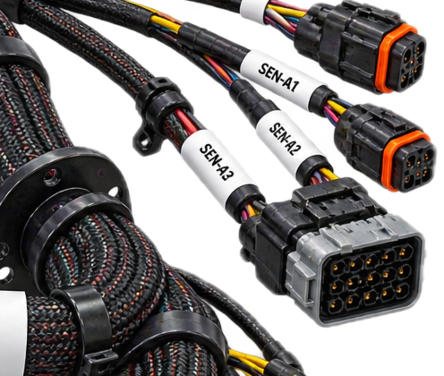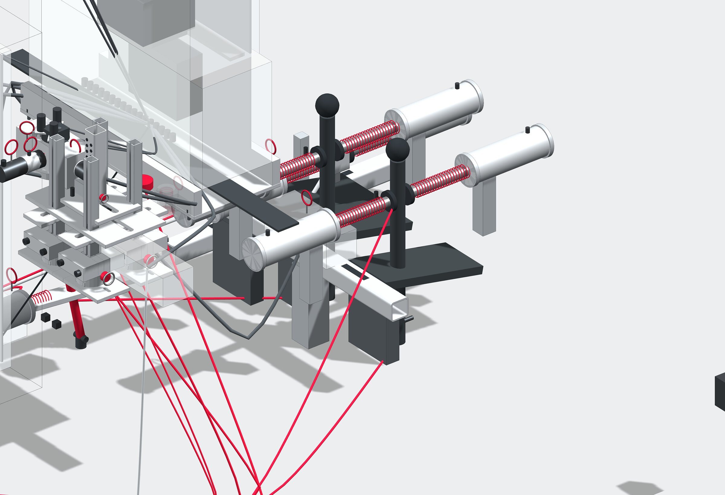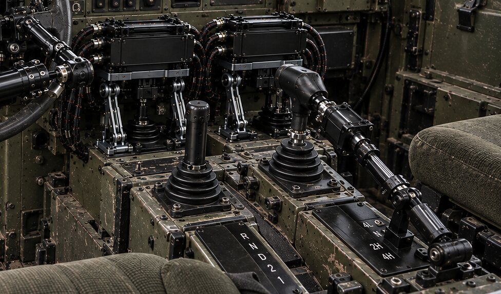
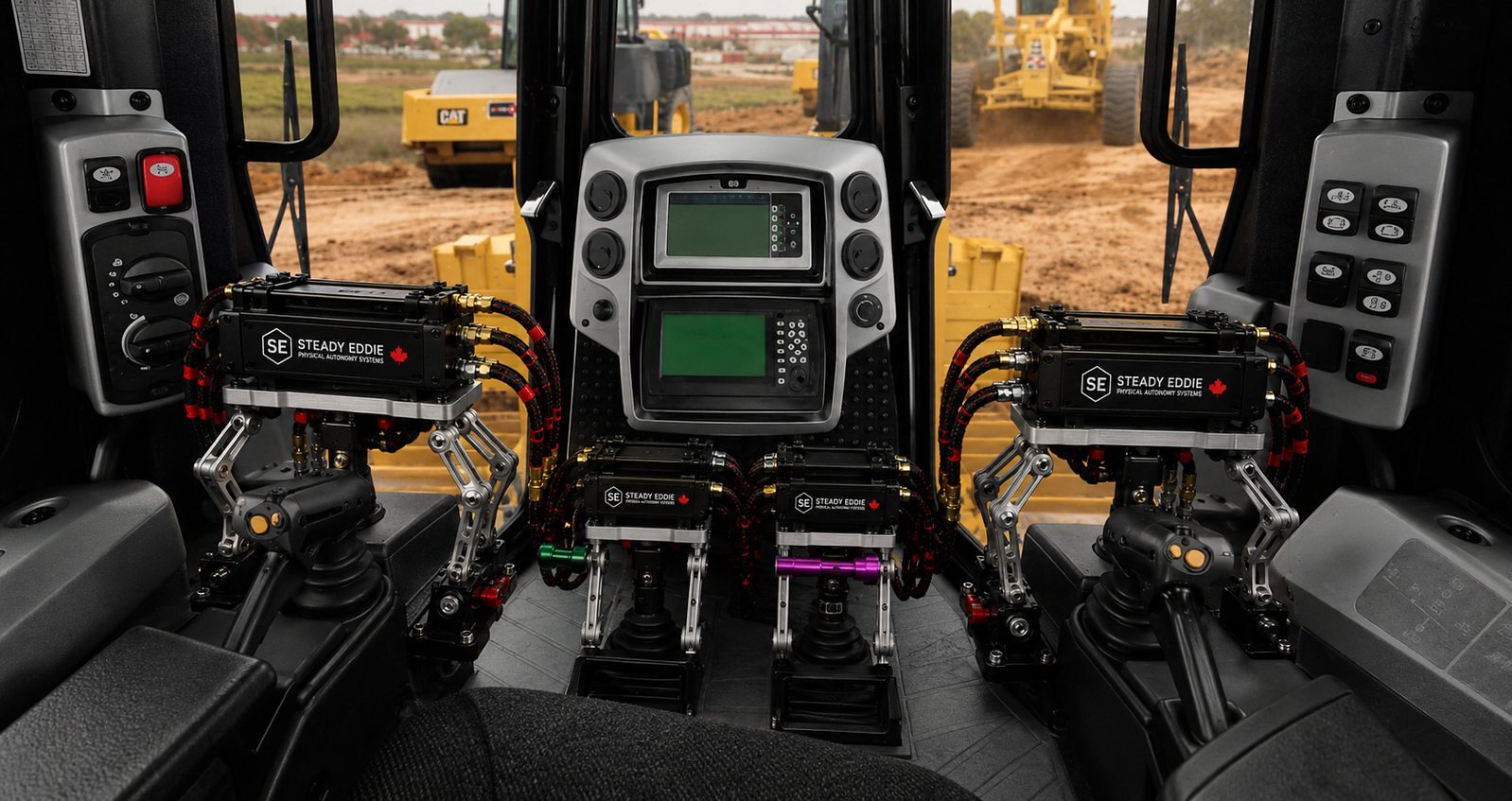
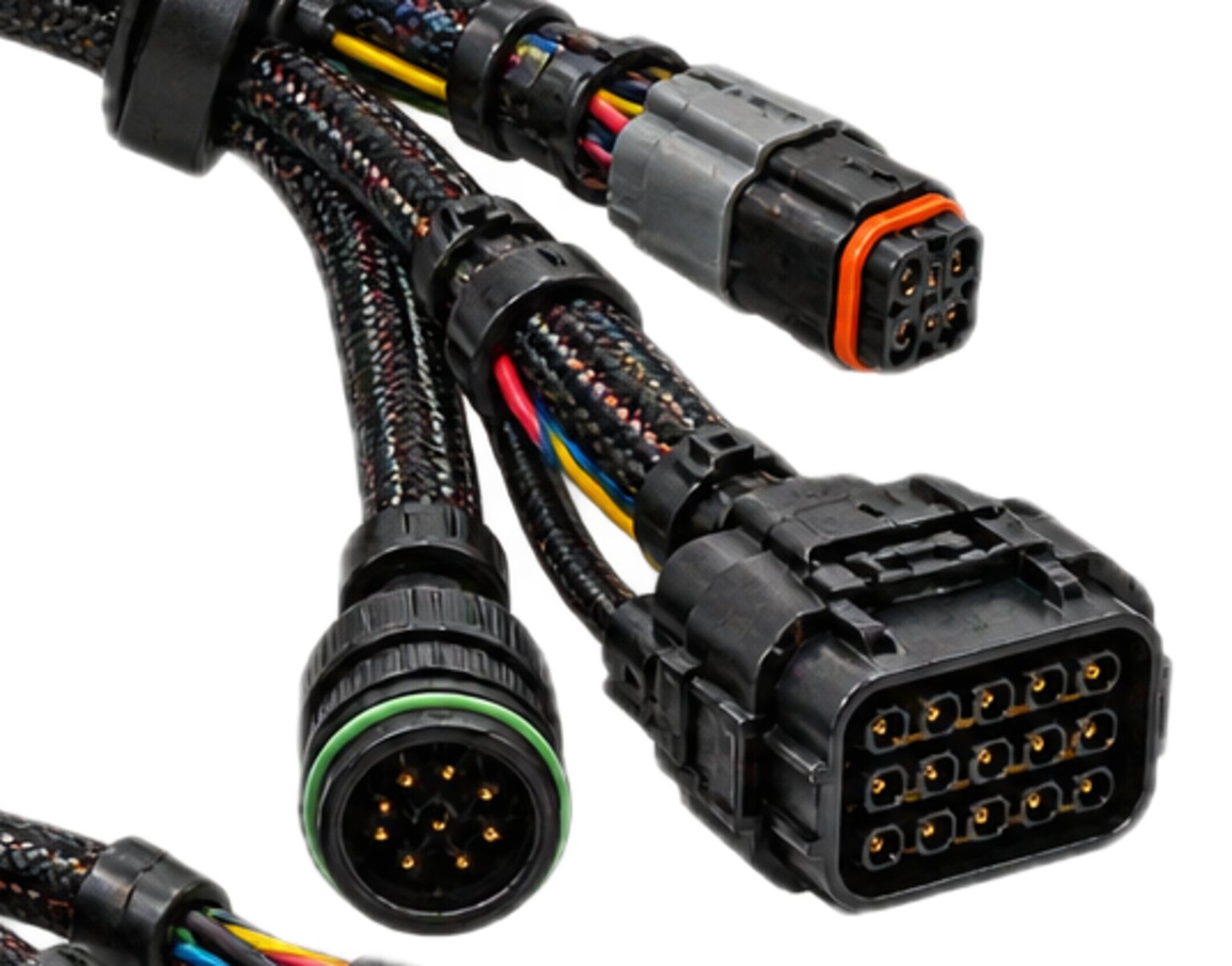
An autonomy kit does not rewire a host machine's controls. It reaches them the way the operator did, by moving them. A linear actuator on a lever, a rotary actuator on a steering column, another on a pedal, another on a switch bank: each sits where a hand or a foot used to be, and each has to be driven and has to report back. The drive is the motor feed; the report is the feedback from a position sensor that says where the actuator went. The two travel the same route, because there is only one route to the actuator, and they must not travel it together. The actuator motor and feedback harness carries both, along one path, as two things that never touch.
It is one harness and not two because the drive and the feedback are one loop: the controller commands a position, the drive moves the actuator, the sensor reports, the controller corrects. The loop is only as good as the conductor that closes it.
The mechanism
For each actuator the kit fits there is one drive cable and one feedback cable, and both run from the drive enclosure to that actuator. The topology is a star: no actuator shares a drive conductor, a feedback return or a shield with another. The drive cable carries the motor feed. For a brushed actuator that is a pair whose polarity reverses to reverse the motor; for a brushless or stepping actuator it is a set of phases; for a proportional valve on a hydraulic control it is a coil pair. The drive pair is twisted along its length so that the field of the feed is cancelled by the field of the return.
The feedback cable carries the position signal and the sensor's supply. What the signal is depends on the sensor the programme has specified: a potentiometer's wiper between its two ends, an encoder's quadrature pairs, a resolver's windings, or the commutation sensors inside a brushless motor. Whatever it is, it runs as twisted pairs under an overall braided shield, in its own jacket, with its own return, and it connects at the actuator through its own shell. The shield is bonded at the end where the signal is read, at the controller, and left isolated at the actuator, unless the drawing states otherwise. The shop does not decide which end.
The two cables share a route and the same clamps, separated by the spacing the drawing states, and are never in the same tie, the same jacket or the same shell. At the actuator there are two connectors, one for the drive and one for the feedback, keyed so that neither plug enters the other's socket, and from two shell families that are different in the hand, so that a fitter can tell which is which by touch.
Every actuator loom crosses a moving joint. The actuator is mounted on the control it drives, and the control moves: a linear actuator on a lever pivots on its clevis with every swing of the lever, and a rotary actuator on a column turns with it. A console, a seat or a cab that moves adds a joint of its own. Across each joint the cable is flex-rated: fine-stranded conductors, a braided rather than a foil shield, a jacket that stays supple at the cold end of the machine's climate, and a free length anchored on both sides of the joint so that the bending happens in the free length and not at a termination.
What it is engineered to
The interface at an actuator is mechanical before it is electrical. The host promises a control with a travel and a force: a lever that moves through its arc against its own detents and springs, a pedal with a return spring. The kit promises to drive that control through its full travel and no further, at the force the control needs and no more, and to know where it is at every point of the travel. The actuator keeps the first two promises. The harness makes the third possible.

Electrically, the drive stage promises a switched, current-limited feed, and the actuator promises a position signal that is continuous and monotonic over the travel: one position, one reading, in one direction. The controller closes the loop on that reading. The feedback conductor's whole job is to carry that reading and nothing else, and a reading that carries anything else is a reading about something else.
That is why a feedback line beside a motor feed reads the motor instead of the actuator. The drive is switched, its edges are sharp, and a sharp edge radiates into any conductor lying beside it for the length of the run. A feedback conductor tied in the same bundle as the drive picks up the switching along its entire length and delivers a position signal with the motor's signature laid over it. On a potentiometer the signature is jitter, and the controller chases it. On an encoder it is phantom counts, and phantom counts accumulate, so the controller's idea of where the actuator is drifts from where it is, one count at a time, and nothing reports the drift, because the drift is the report. It is a whisper beside a running engine: the whisper is still there, and what you are reading is the engine.
The joint has to survive continuous flex for the life of the machine. Every stroke of the lever bends the cable. A conductor of coarse strands work-hardens and breaks under that, one strand at a time, and presents first as an intermittent at one end of the travel. A foil shield cracks under the same flexing and stops being a shield without stopping looking like one. A cable anchored at the wrong point takes the bend at its termination and fails there. A cable that flexes in torsion rather than in the plane of the joint fails soonest of all.
It also has to survive the fitter. The actuator connector is the one in this kit that gets unplugged most: to service the actuator, to free the control for a person, to remove the kit. It gets unplugged under the console, by feel, with gloves on. It has to seal against wash-down when mated, latch so that vibration cannot walk it apart, and release with one hand. The feedback shell has to protect its contacts when open, because a supply contact bridged to a signal contact by a wet mating is a position reading that is confidently wrong.
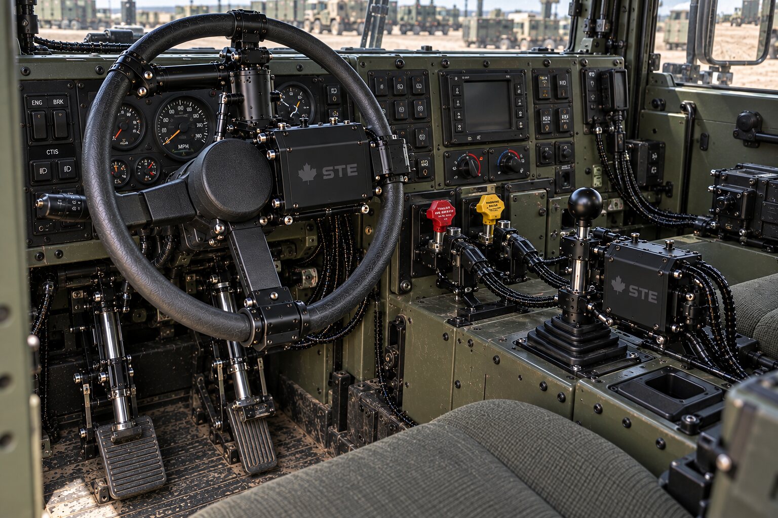
Every conductor carries its circuit identity, end to end.
The discipline applied to this harness
The drive and the feedback are segregated along the same route: two jackets, two shells, one set of clamps, a stated spacing, and a right-angle crossing wherever one must cross the other or the power distribution loom. The feedback is twisted so that what couples onto the pair cancels at the input, and shielded so that what couples onto the shield drains to the controller's reference. Nothing is done to the feedback to make it tolerate the drive; the drive is kept away from it, and the shield is there for what gets through anyway.
A shield bonded where the drawing bonds it is a shield against one thing. Bond an end the drawing left floating and you have made a loop through the machine's chassis that carries a current you did not design, and on a feedback shield that current is added to the signal the shield was there to protect. The feedback shield is bonded at the controller and isolated at the actuator; the drawing states it and the test proves it. Where a shield lands and why is on the shielding and bonding page.
Every conductor carries its circuit identity, end to end. On this harness that sentence is written for the fitter under the console with a lamp in their teeth. Each cable carries its actuator's identity and its function, drive or feedback, at both ends and along the route, and both connector shells are labelled so that the fitter reads the label and not the drawing. The keying makes the wrong mating impossible. The labelling makes the right one obvious.
Routing across the joint is stated on the drawing and fixed on the machine: the free length, the anchor either side of it, the plane of the bend, and the clearance from the control's full travel, so that the cable is never tight at either extreme. The loom runs clear of the neighbouring actuator's drive, which is as noisy to this feedback as its own.
Test is per assembly and against the drawing. Continuity proves every conductor lands in the cavity the contact map gives it. An isolation test asks whether the drive and the feedback, which must never meet, are in fact separate, and it is run on every finished assembly before it leaves. A sense check proves the drive turns the actuator the way the drawing says and the feedback increases the way the drawing says, because a reversed drive pair drives the control the wrong way as hard as it can, and a reversed feedback is a loop that runs from its target. Then the actuator is exercised through its full travel with the harness fitted, and the cable has to make that travel without tightening, catching or bending at a termination.
Done badly, this harness fails quietly and then all at once. Feedback in the motor's jacket reads the motor, and the loop hunts. A foil shield across the joint cracks, and the position signal grows noisier over months while every reading still looks plausible. A lost position signal is the worst of these, because of what it does to a machine with nobody in the seat. On a crewed machine the operator feels the lever go wrong and lets go. On this machine the controller has a drive and no measurement, and a controller that cannot see its actuator either stops or keeps driving into the end stop. The programme's controller decides which, and the stop chain exists for the moment it decides wrong. What the harness owes is that the loss is visible where it can make it so: a half-mated connector must not report a position from the wrong contacts, and it is the interface, not the shop, that decides whether an open conductor reads as an impossible position or as a plausible one. A signal that fails loud is a fault. A signal that fails plausible is an accident that has not happened yet.
How it is bought
The machine programme owns the design and the drawing master. It issues the set: the actuator schedule with each actuator's drive type and sensor type, the drive enclosure's contact maps, the connector schedule, the shield and bonding intent, and the routing intent across each joint. We build to that issued set and we return the manufacturing detail to it. The design authority for the kit is the programme's; the shop pack we produce is built to it and owed back to it.
From the issued set we perform the takeoff and produce the shop drawing: each cable with its identity, each conductor with its cavity, each shield with its landing, each anchor with its position. The shop drawing is walked on the machine before it goes to you, so the lengths on the drawing you sign are the lengths that were measured, and nothing is fabricated until it is signed. We walk the machine, with the actuators mounted and the controls swung through their full travel, and every length is fixed there, because the free length across a moving joint cannot be taken from a drawing. A value nobody measured never reaches a wire.
The build carries a per-assembly record: which conductor, which contact, which crimp, which shield landing, which test, and what that test showed on that assembly. The record and the full shop pack return to the programme's drawing master, so that the next kit is built from the record and the programme's own set is complete without us. An electrical assembly built for sale or installation in Canada is governed by CSA certification and the Canadian Electrical Code. The components we specify carry their own certification. The approval route for a finished, project-specific assembly is confirmed with the certifying body for that assembly before it is built, and we tell you where yours sits before we build it, not after.
To start, send the issued set, or the actuator schedule and the interface specification if the set is not complete, through the enquiries page, and tell us which controls the kit takes over and what moves. We answer with what the takeoff needs, and with what the walk has to see before a length is cut. We do not run feedback in a motor's jacket, we do not put drive and feedback in one shell, we do not put a foil shield across a joint that moves, we do not take a flex length off a drawing, and we do not fabricate ahead of a signature.